Don’t you think it’s been warm this year?
With such a massive typhoon coming, that’s definitely abnormal weather.
We’ve gotten a glimpse of all sorts of issues with high-rise apartments, so… let’s get to work. (Meaningless)
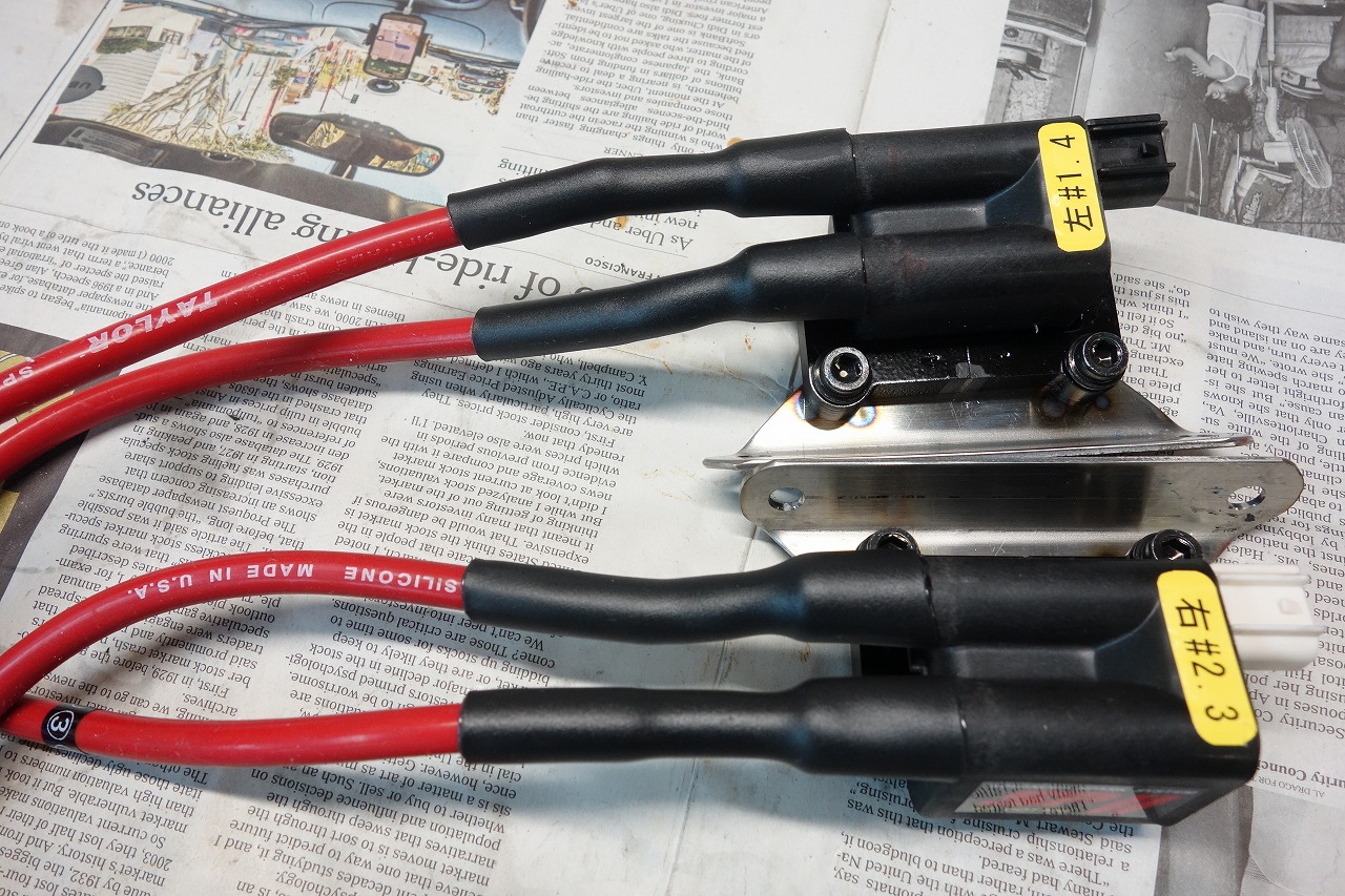
Installing the AS Watanabe full power kit.
Since they wanted to keep the red wires (original) if possible ♪, we cleaned them up and reused them.
There was no terminal to insert into the coil, so we installed one from our spare stock.
As usual, we secure the wires with 1/3 and 1/4 heat shrink tubing.
1/3 = 1/3 shrink (adhesive-lined) )
1/4 = 1/4 shrink (adhesive-lined)
Since 1/3 and 1/4 shrink, they become thicker.
• Excellent for leakage protection
• Excellent for preventing disconnection
• Excellent for waterproofing
The downside is that you have to cut them to remove them, but since they’re large, replacement is easy.
Considering the risk of accidental disconnection, I think this approach offers better safety including serviceability.
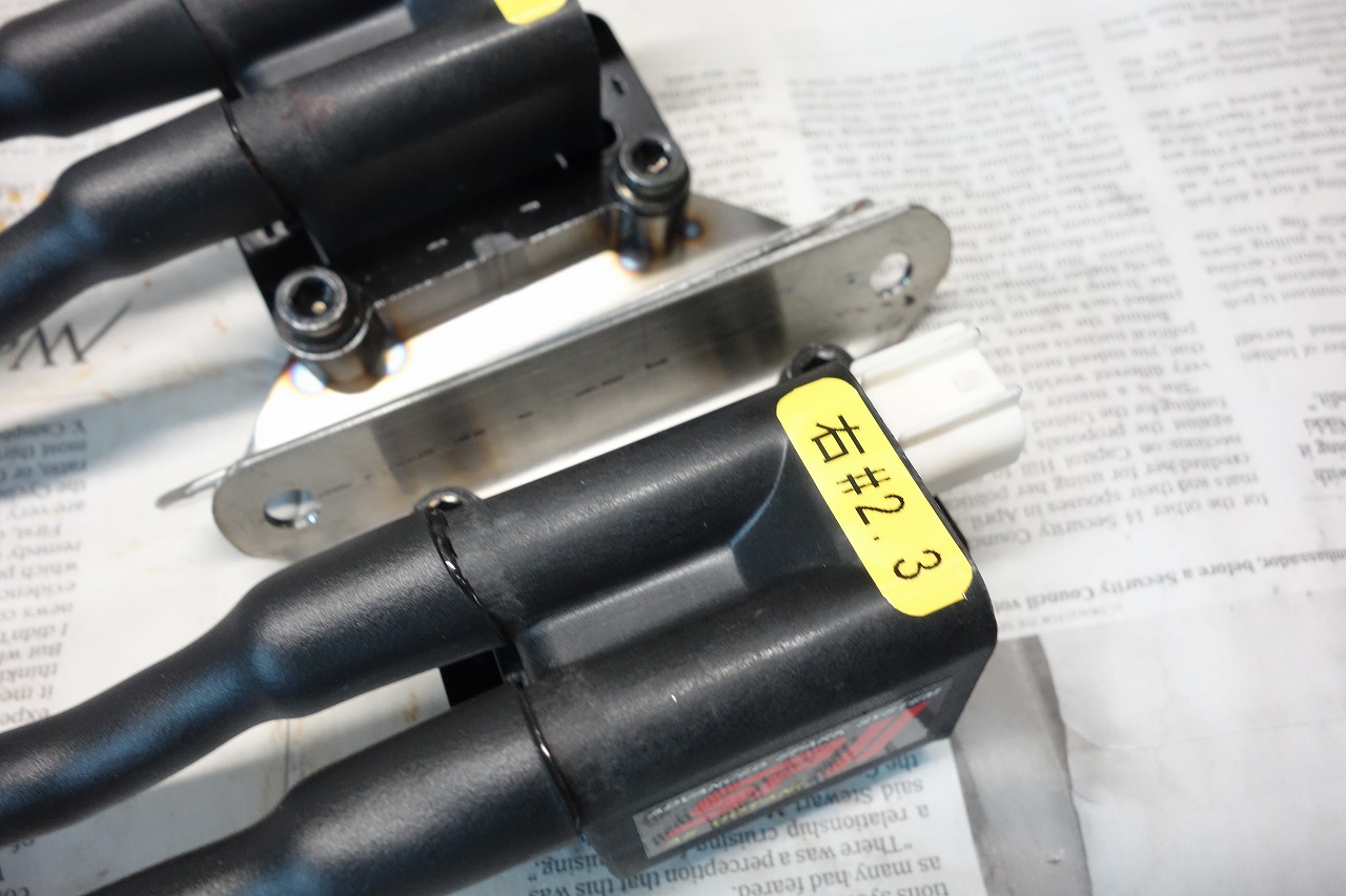
We’re also labeling the coils. Being able to understand at a glance with a “pop!” makes work faster. It’s the kind of thing that makes the world a kinder place when anyone can work on it in the future.
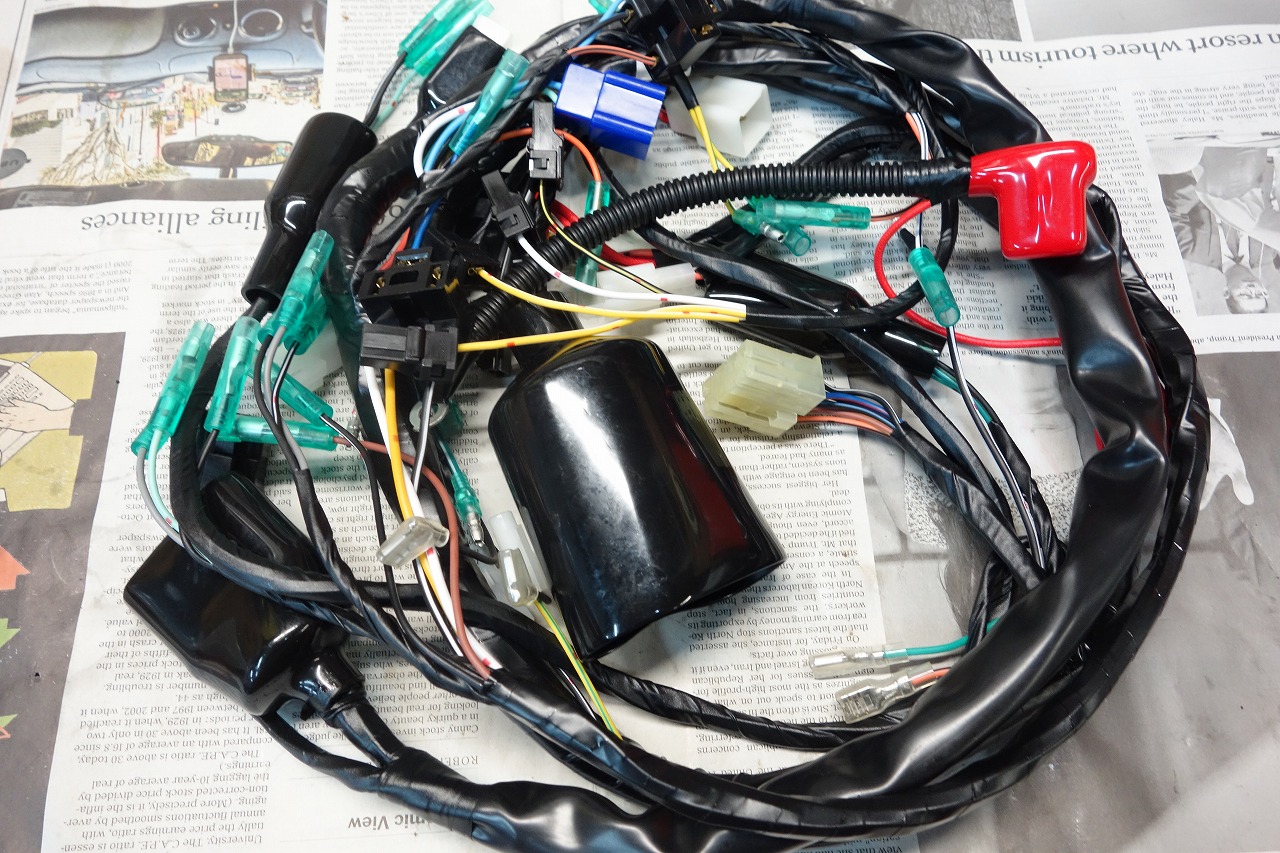
The repro harness they brought in.
The instructions are also kind and detailed.
Since it’s semi-universal this time, I was actually puzzled.
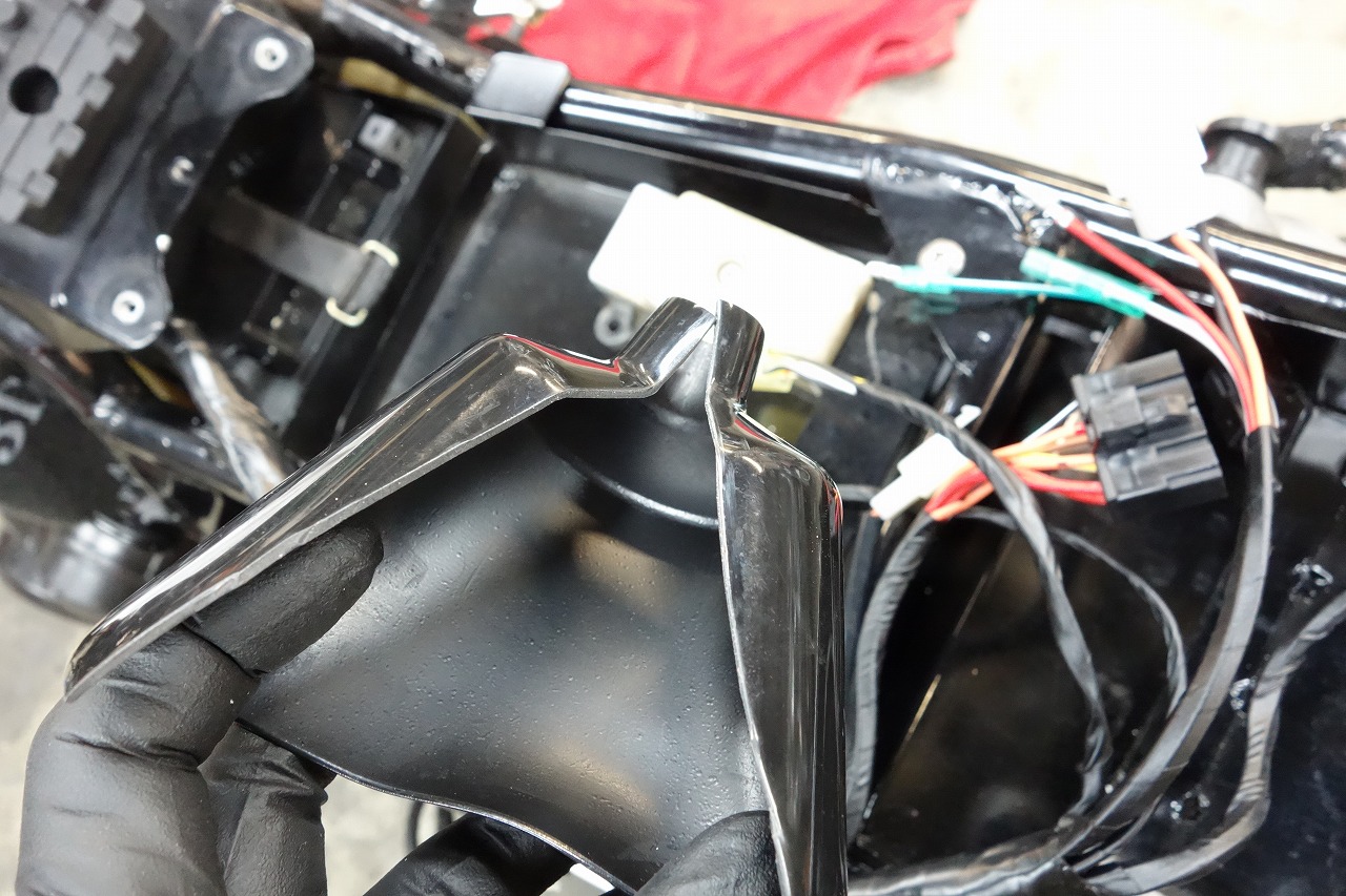
It’s the type where you just cut away unnecessary covers. These OEM covers are a pain to plug and unplug. I sometimes wonder if they’re really that waterproof.
Heat-resistant (150°C) braided tubing and larger items like that offer better workability and appearance.
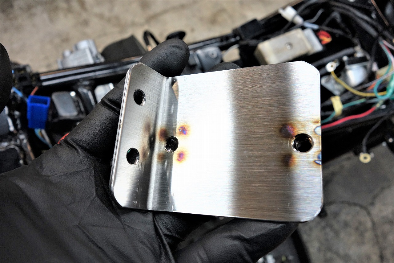
I made a bracket for the step-up kit.
We want to keep it looking clean and minimal on space, so we’re working hard to fit it in.
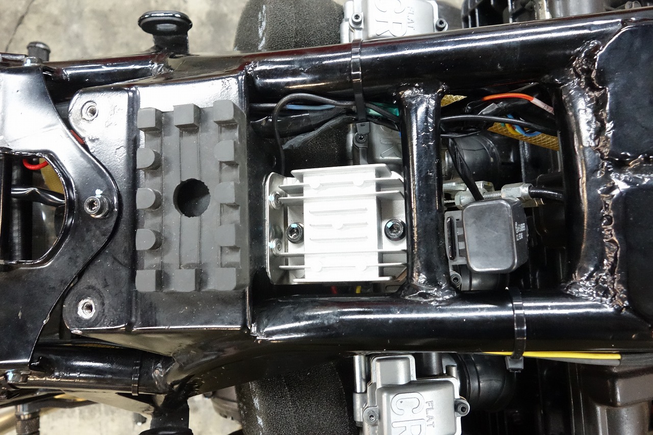
It fits under the tank.
* We’re worried about an immediate defect.
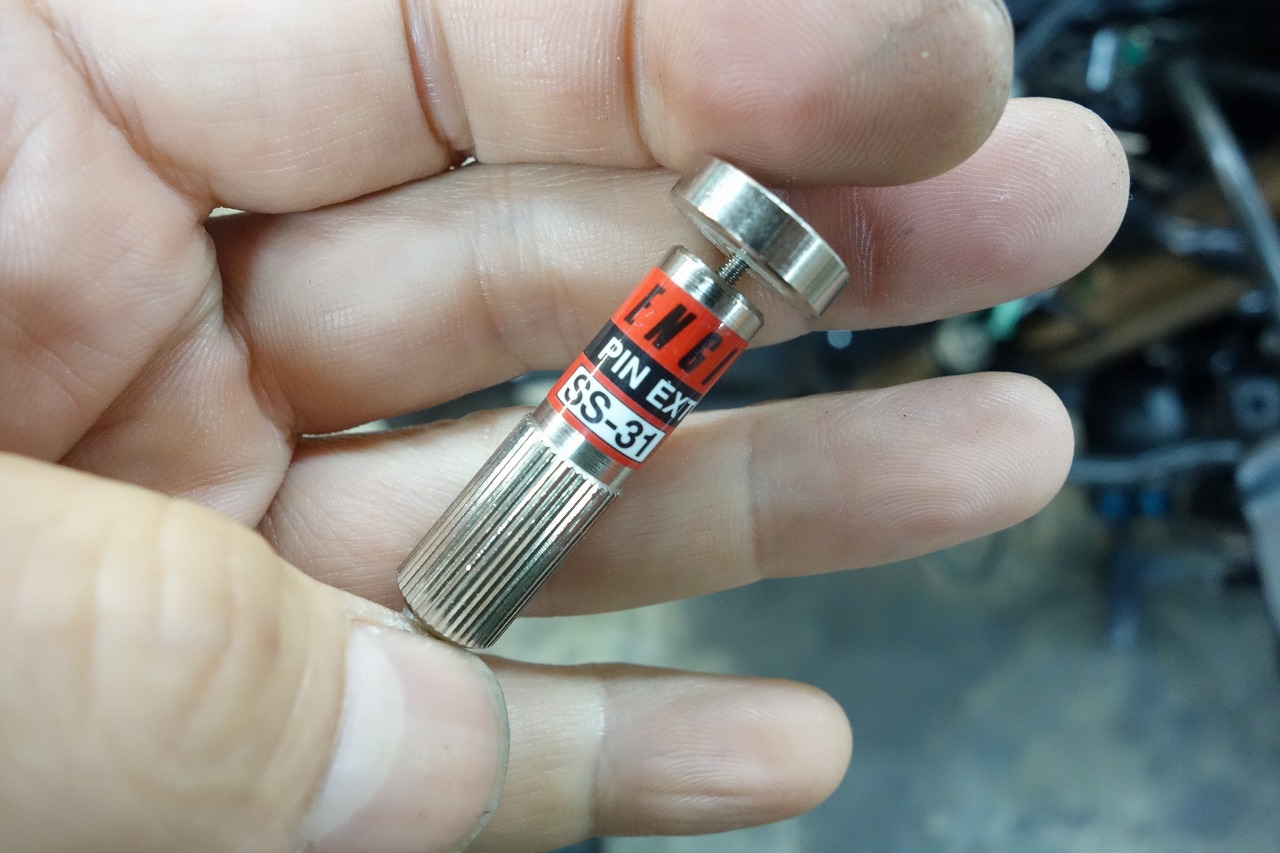
Removing terminals from inside the meter connector on the Katana (GSX1100S, 750S).
This is really great.
Engineer pin removal tool SS-31
- You can easily remove terminals inserted into the housing.
- Size: Overall length 97 mm
- Sleeve outer diameter: φ2.7 mm
- Sleeve inner diameter: φ2.1 mm
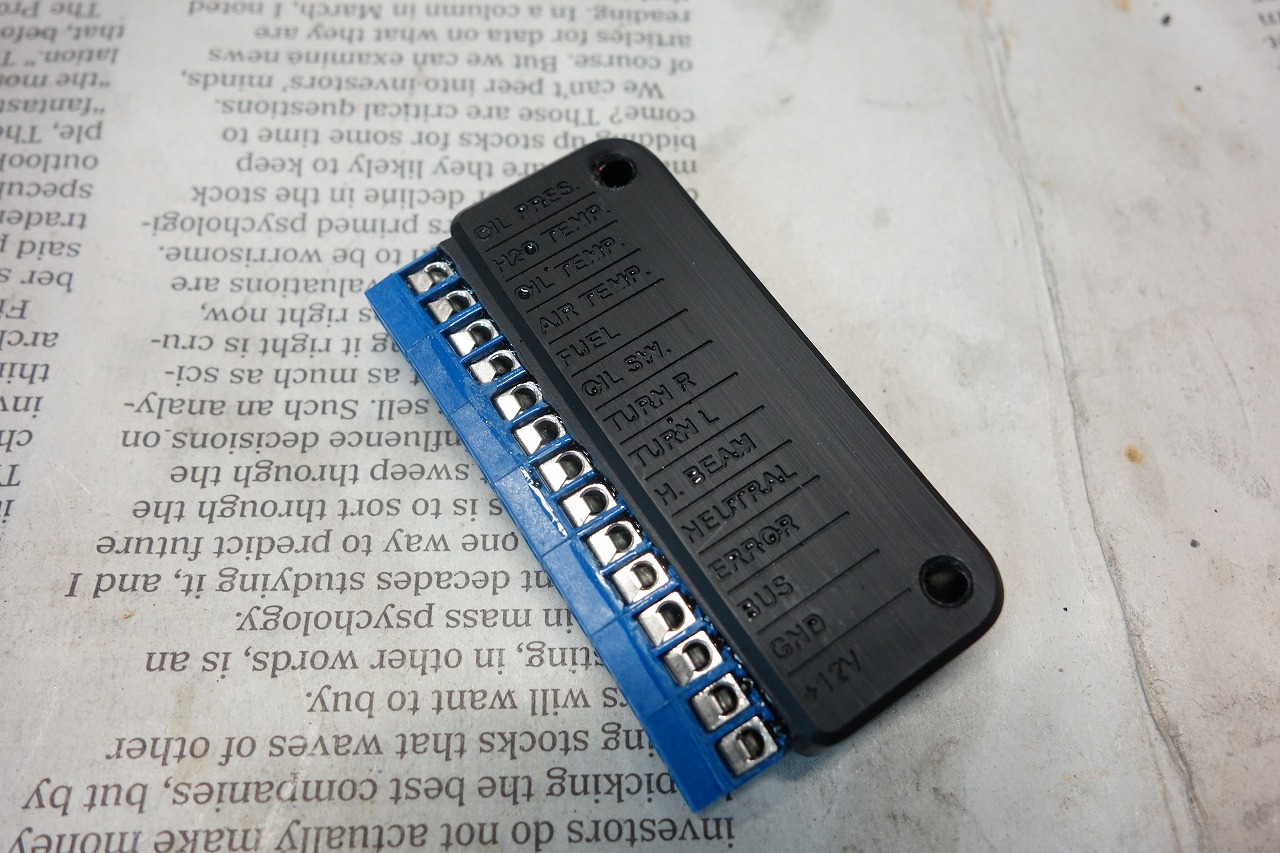
Breakout Box B
An item that’s easy to connect.
I don’t think it compares to the m-button … but it seems to be something different.
With all these options coming out, I’m not sure anymore.
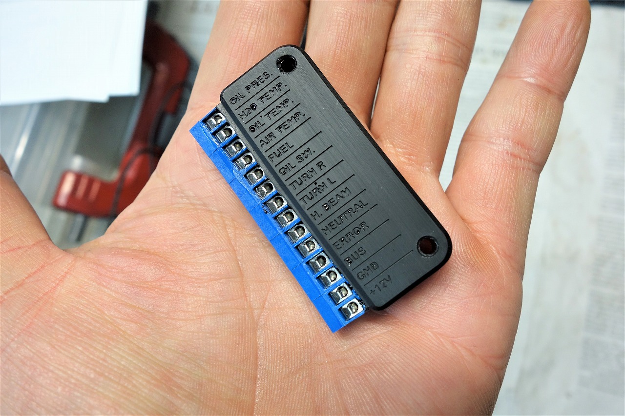
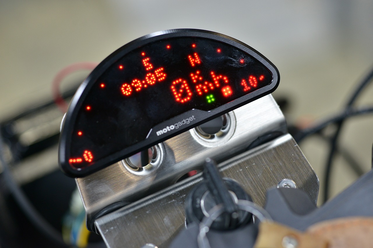
To show you how small it is, see the image.
Too big is a problem, too small is a problem… it’s tricky.
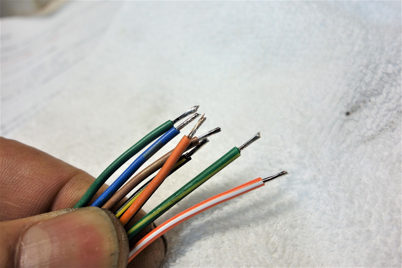
Since thin wire breaks easily, I went with 0.5 SQ.
Breakout Box B You insert it and tighten the screw to clamp it, so I soldered it thicker to make it less prone to breaking.
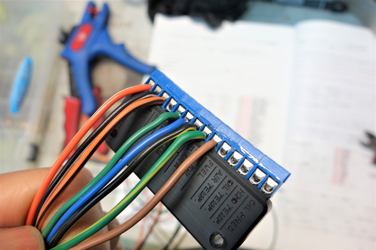
This is how it turns out.
If you need other sensors, you’ll need to connect them.
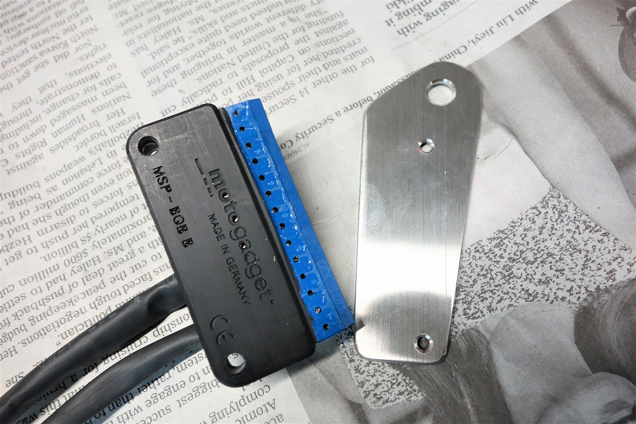
If you fix these small parts with cable ties, when you remove them later you think “oh no…”
or something like that, right?
Since it’s SUS304 T=2 MM, the threads are cut and it’s self-locking.
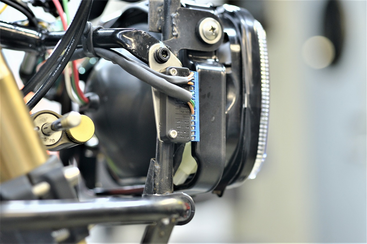
That’s the idea.
• Water shouldn’t get in as much as possible
• Serviceability should be good (with future additions in mind)
That’s the approach.
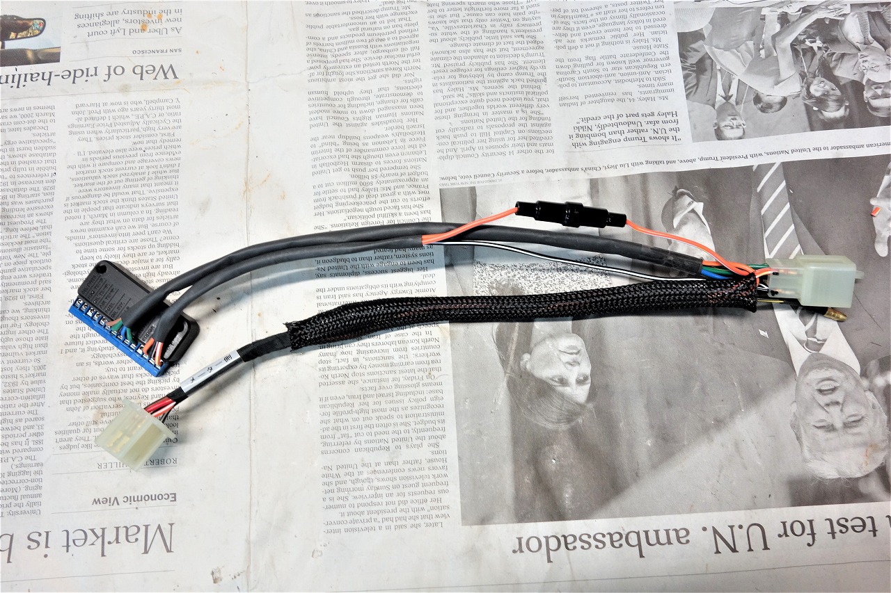
Breakout Box B This is the sub-harness that connects the meter and harness.
I always think that if you just install it, it’s probably quick.
But when you think about disconnecting it or troubleshooting, you need to make sure it can be disassembled.
Considering the layout, I’m left wondering “hmm? uh-huh?” and the worries never end.
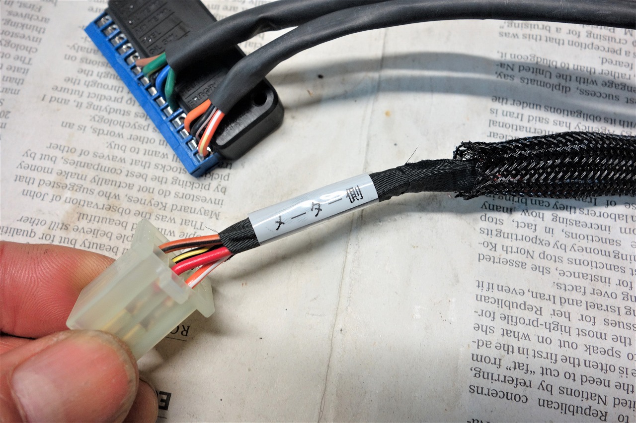
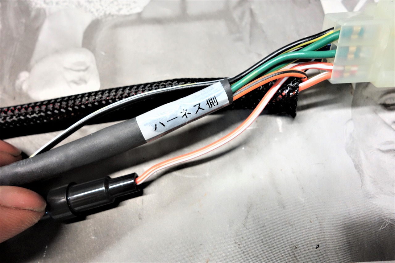
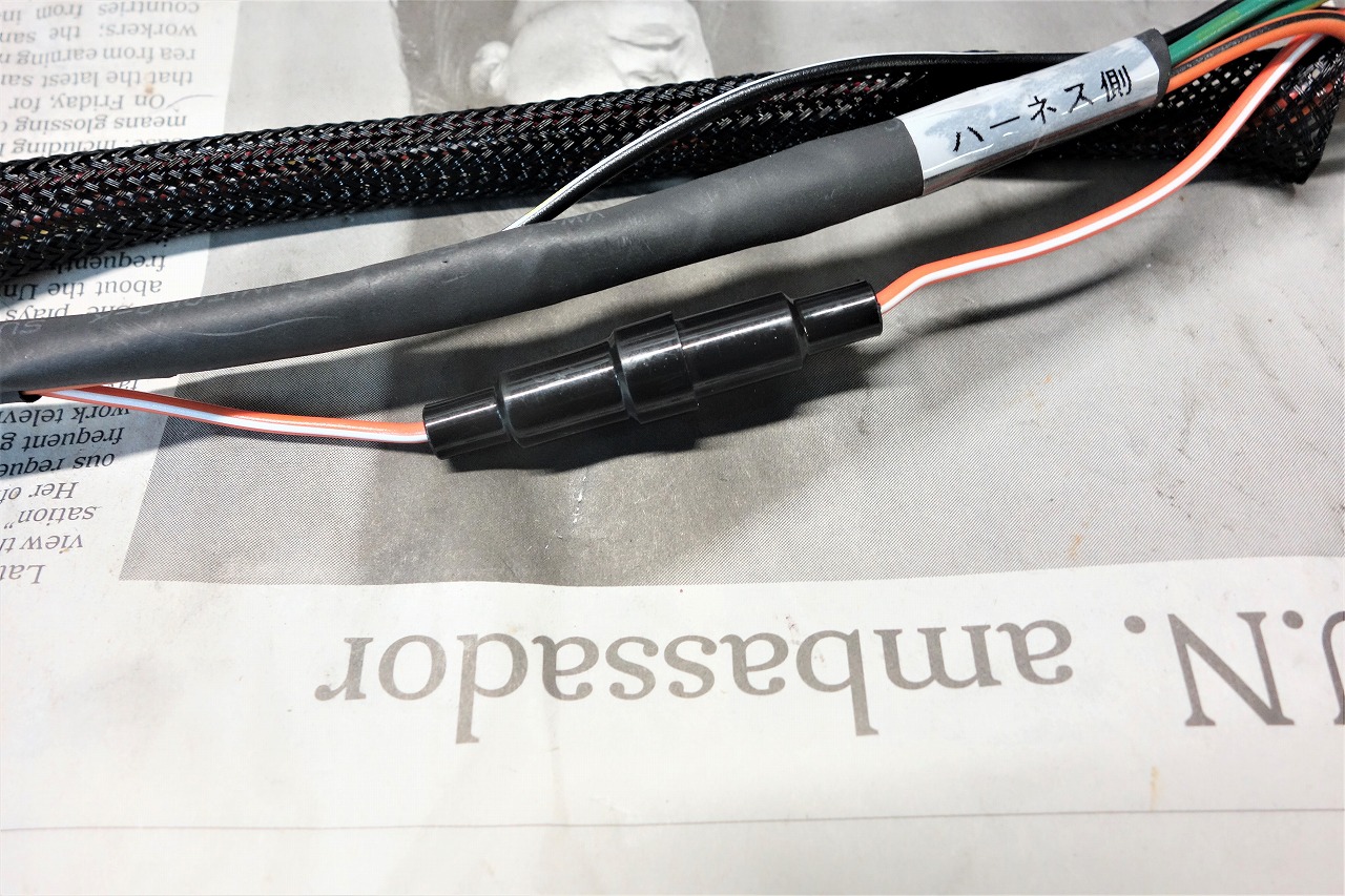
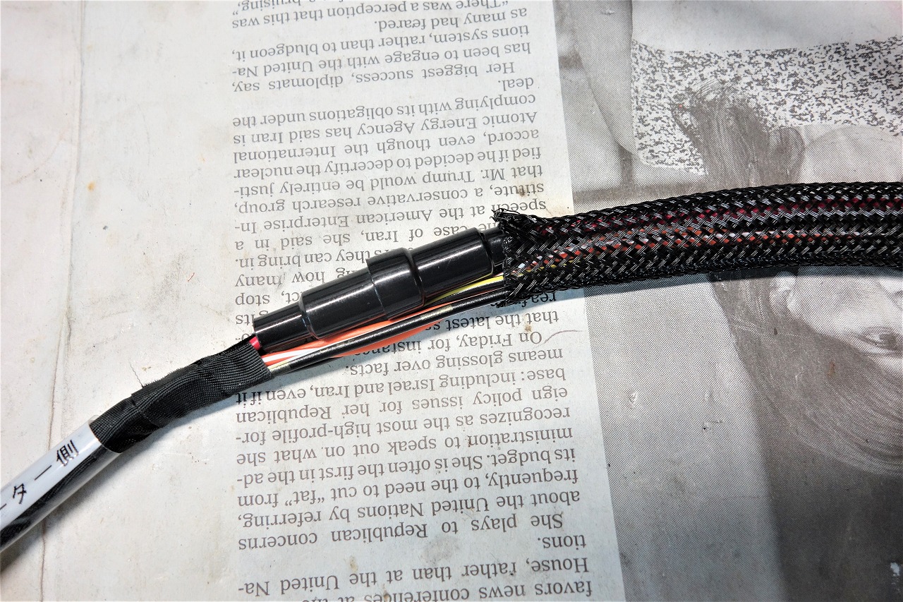
Only one mini fuse (1A) was included.
So we really need another one.
I had no choice but to use a fuse from my own Motogadget to build it.
I really felt the need for mini fuses. (Vertical wire layout is easier and looks better)
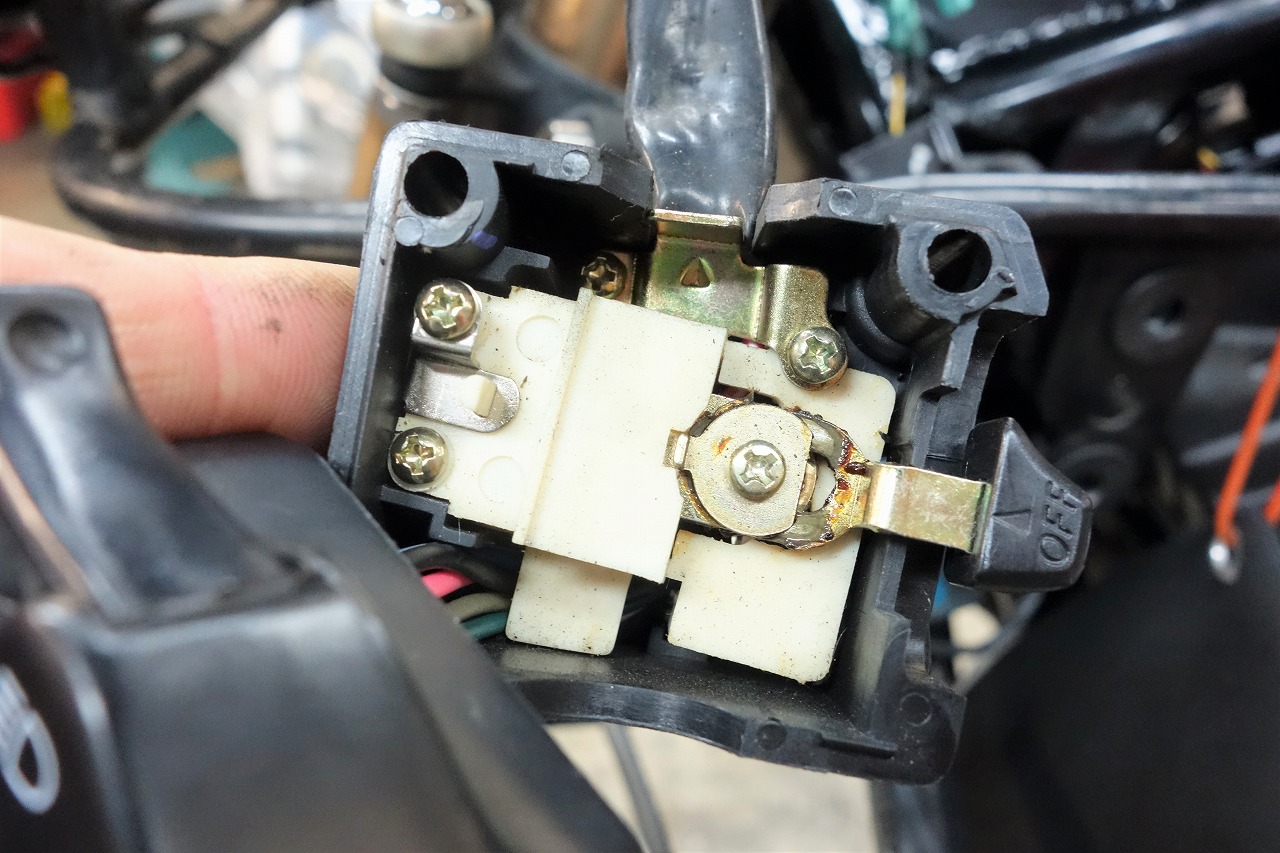
Plan to put the settings switch on the passing light.
I thought I could disassemble it just by removing the screws, but… unclear.
Plus it looks like a repro switch, so we gave up.
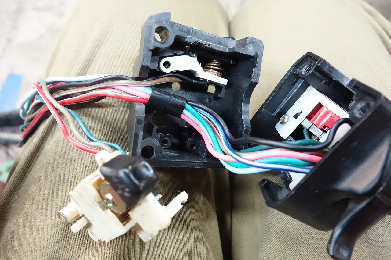
I noticed the tabs on the back were hooked in and managed to disassemble it.
Now I can trace the colors.
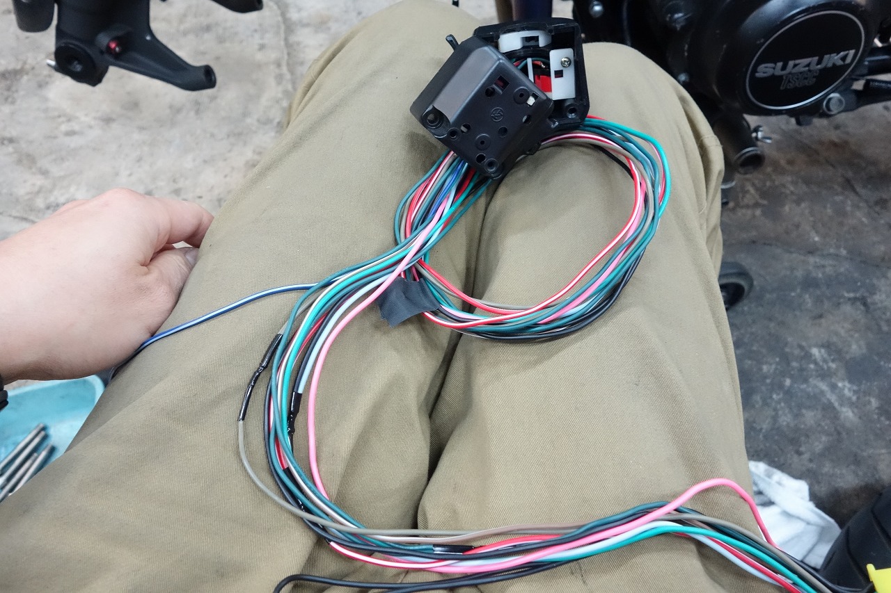
( ,,`・ω・´)Hmm? When I put the tester on…
The colors are different between the switch side and the connector side.
That means it’s branching inside, so I stripped the outer sheath to check.
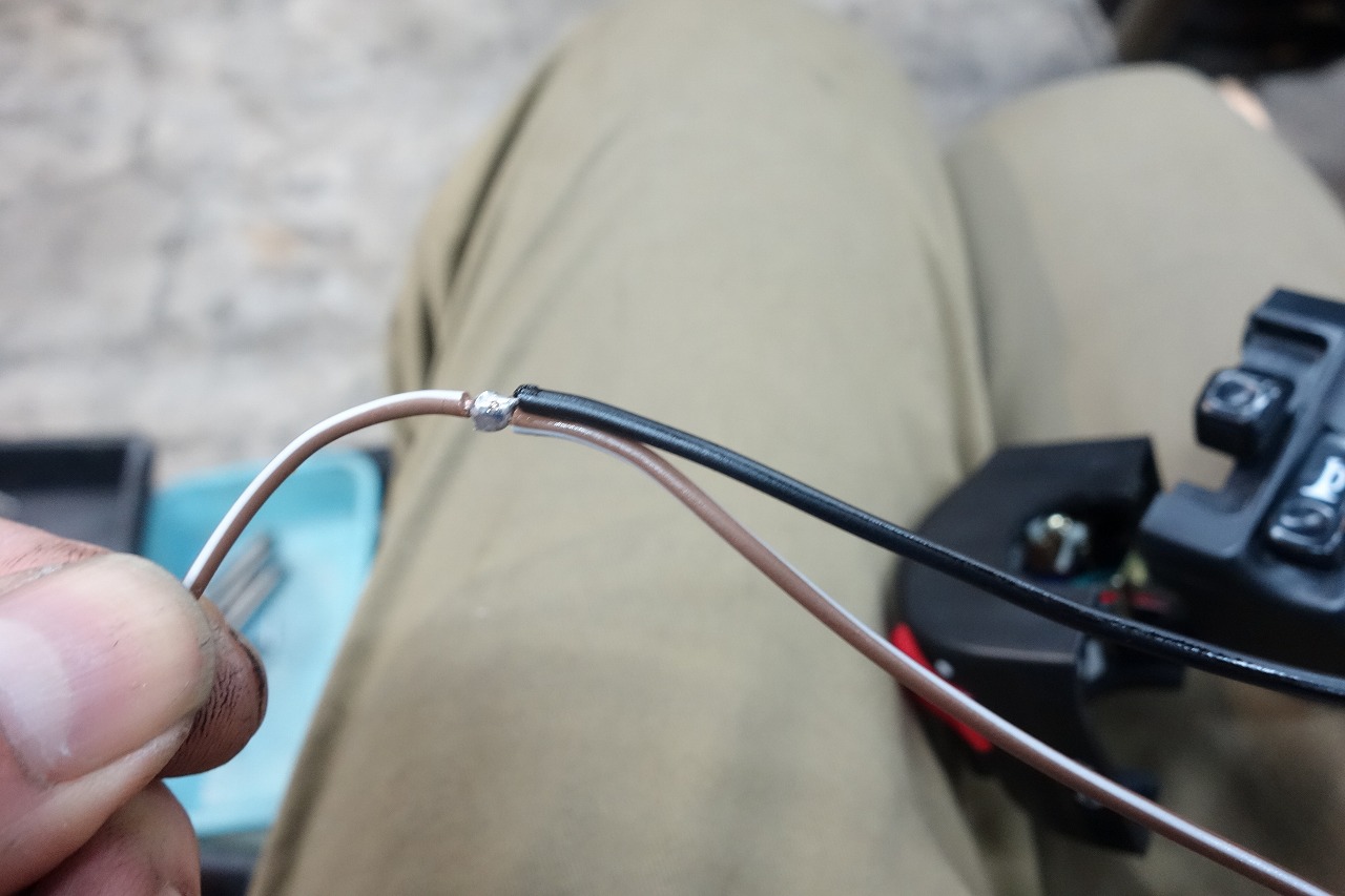
They were merging here, so we cut, covered, and set it up so the ground drops inside and then covered it.
It’s incredibly tedious and time-consuming… can you tell?
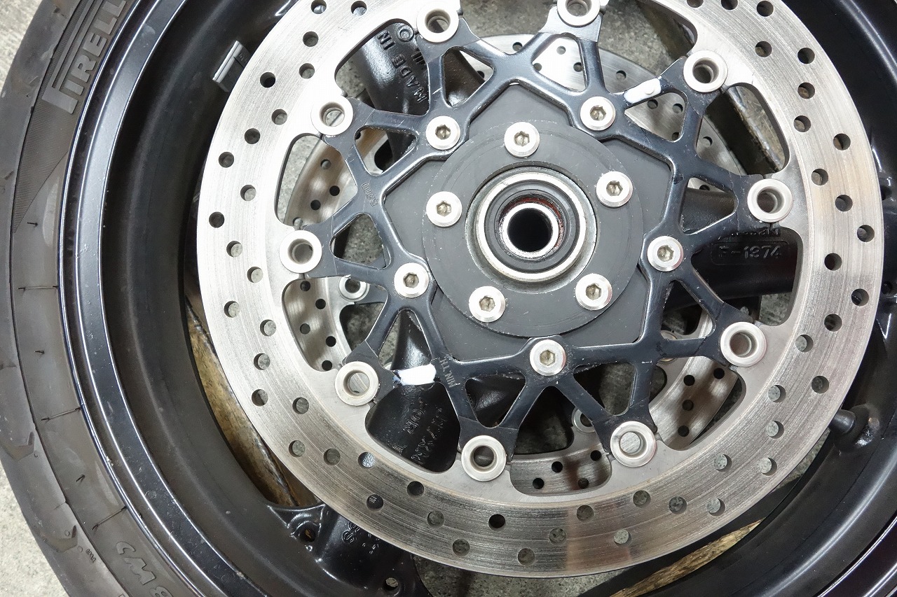
A magnet… in this day and age… there are still meters like that? *It adds work. We remove the wheel and embed it with epoxy. (Cut out unnecessary parts later)
When buying a meter, if possible, choose an inductive proximity sensor (responds to iron) for easier setup and I recommend it.
• Unwanted things don’t stick to the magnet. Iron filings, etc.
• No need to install a magnet
• Can be acquired from the front sprocket (sensor installation only is OK) &More pulses are acquired so there’s less error & speed fluctuation is smooth)
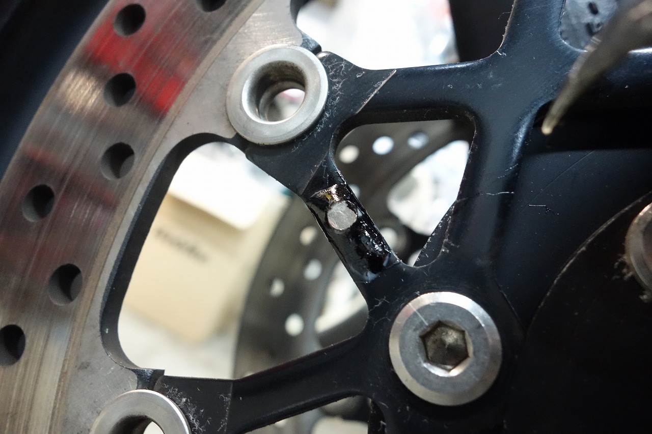
I cut out the necessary areas and made the surroundings black and sticky.
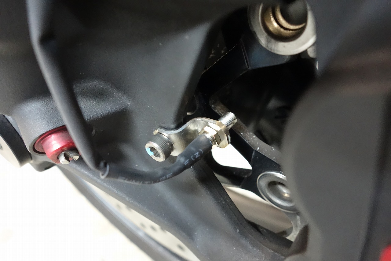
Someone had already cut the threads, so I got it from there.
Sensor (I wish I’d put the magnet further out on the perimeter… I regret it)
*The S-bend is close and tight (SUS304 t=2 MM)
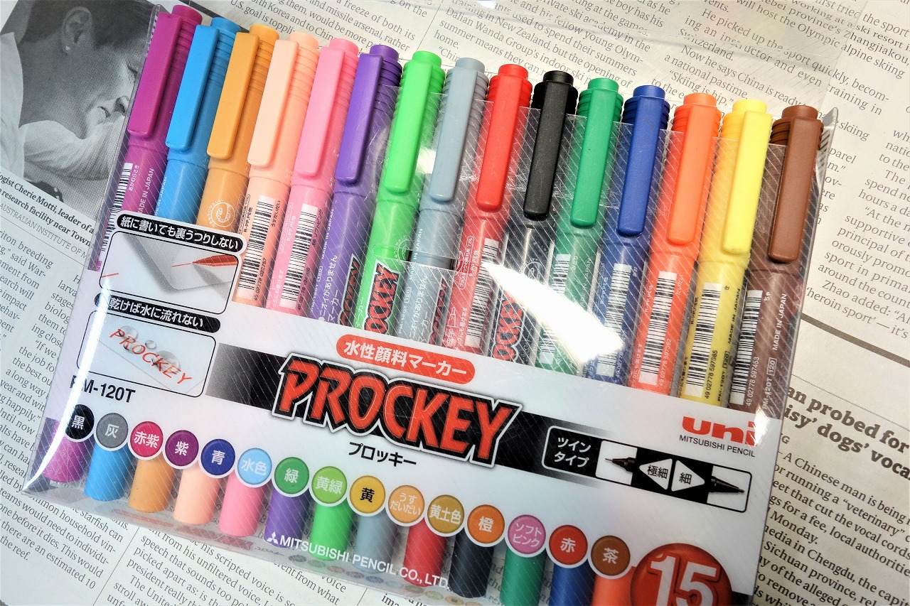
I highly recommend this to anyone doing harness or wiring work:
” Mitsubishi Pencil Water-based Pen Posca Twin Extra Fine 15 Colors PM120T15CN ”
With this, you can cover most situations.
For example, when recording wires,
black/red, red/black, red/blue, blue/black—there’s a risk of getting confused.
Or maybe
B/R, R/B, R/BL, BL/B, and later you wonder “is this right?” If you judge by color, you’re almost 100% confident.
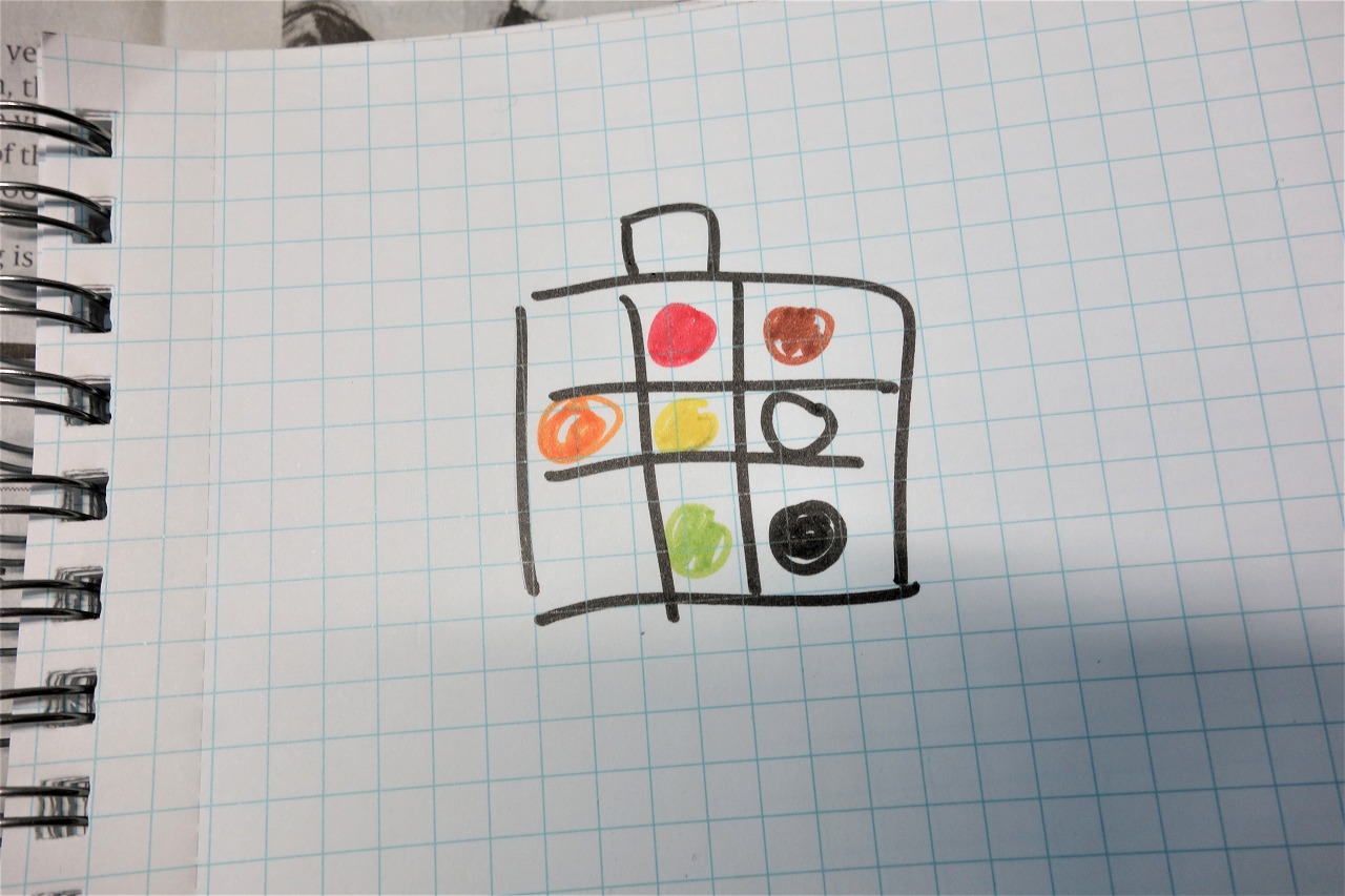
Sorry for the messy notes.
Usually I record it like this, then pull it out and put it back.
Doing it visually is faster and greatly reduces the risk of mistakes.
Work is simpler and quicker.
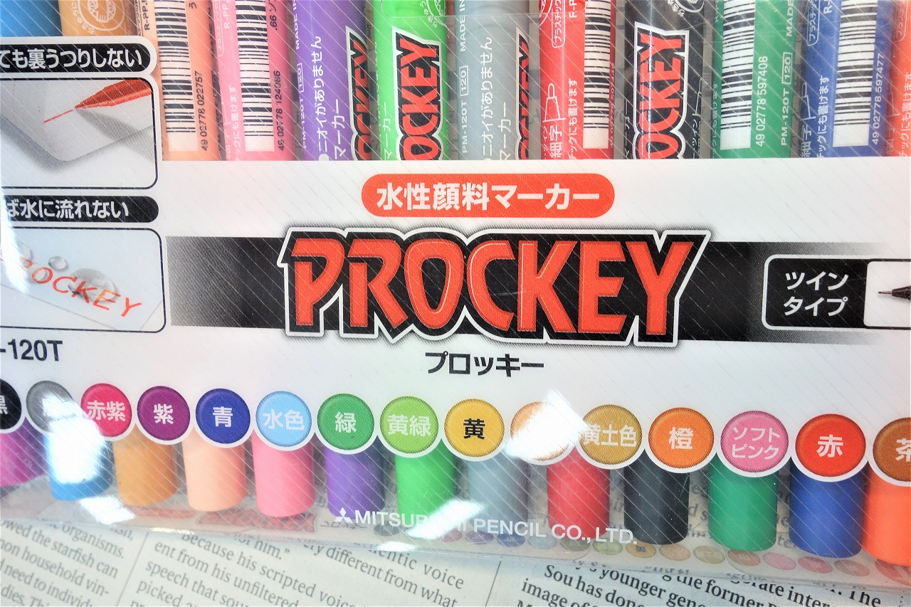
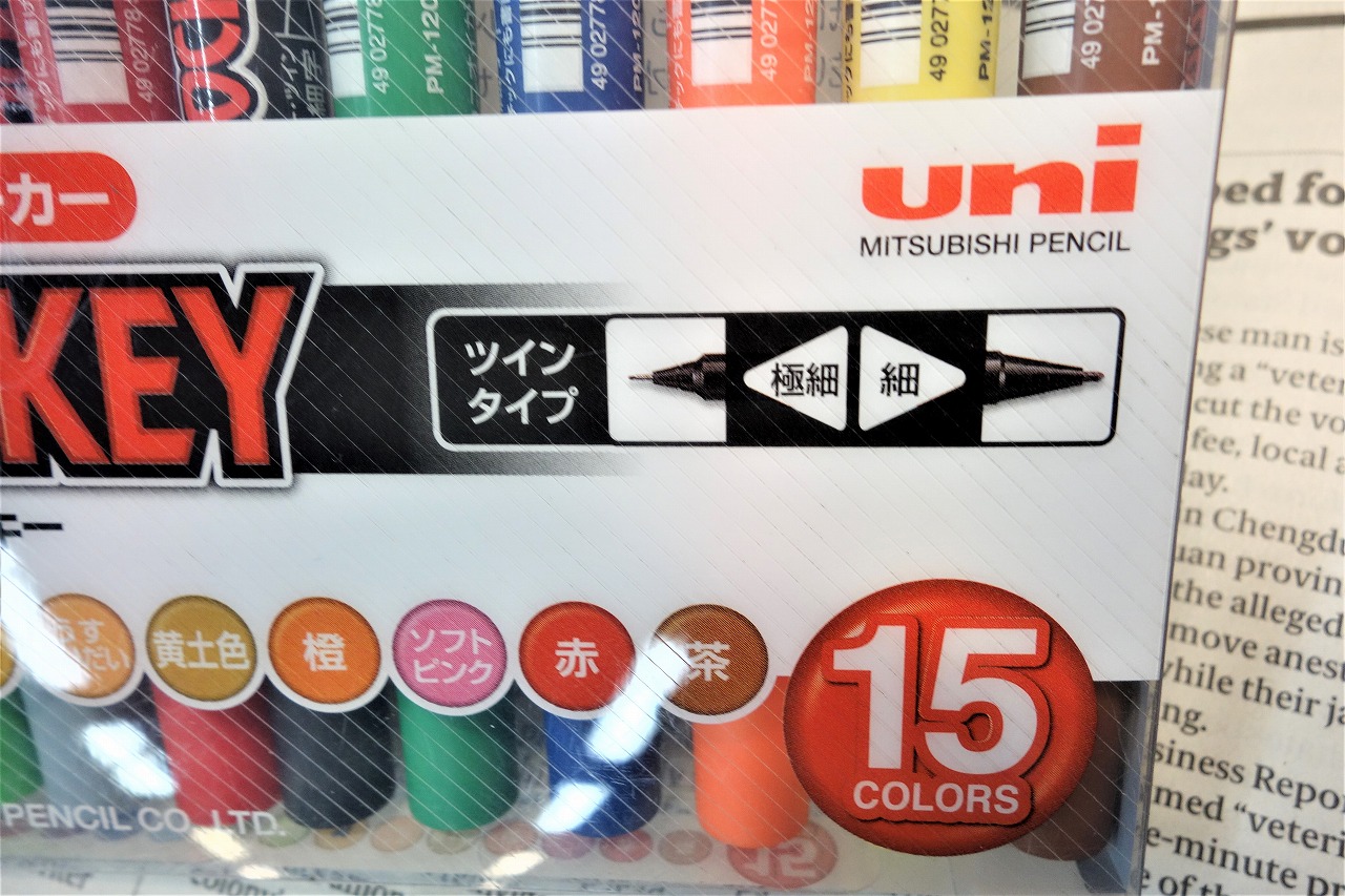
” Mitsubishi Pencil Water-based Pen Posca Twin Extra Fine 15 Colors PM120T15CN ”
15 colors and double-tipped (I probably won’t use the fine tip…)
I’ve tried various things, but this might be the final form.
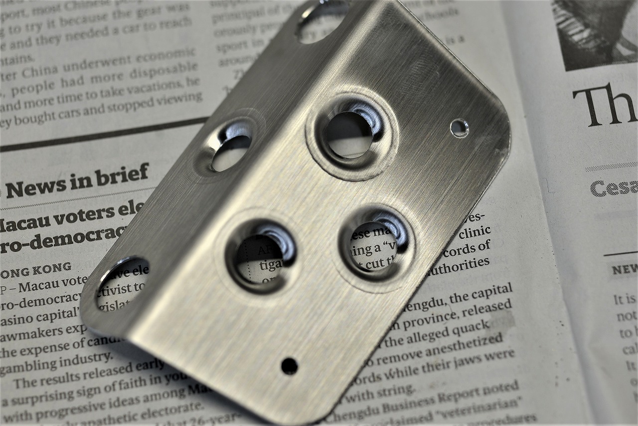
I was torn about the meter bracket… the safe two-piece design.
Basically, if it doesn’t float, there’s a high chance of breaking.
I made it two-piece because repairs are easier.
Later if you think “a bit higher or lower,” you can adjust it.
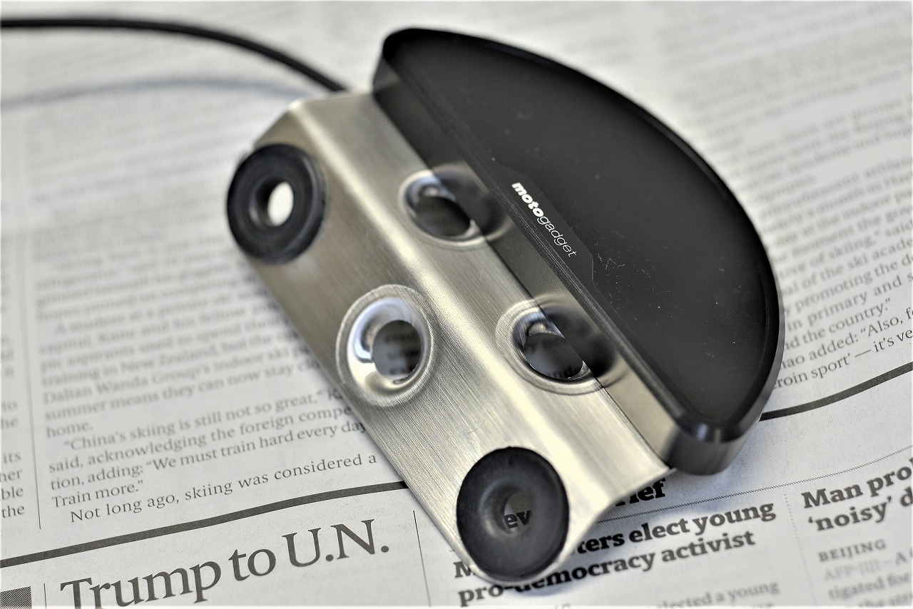
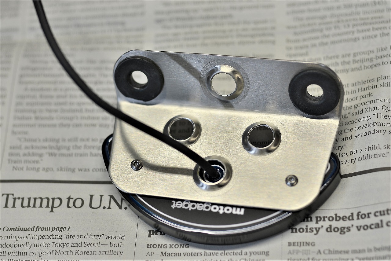
If there were gaps, I wanted to burr them, so I just opened them up.
*Weight-reduction holes are better done as post-processing.
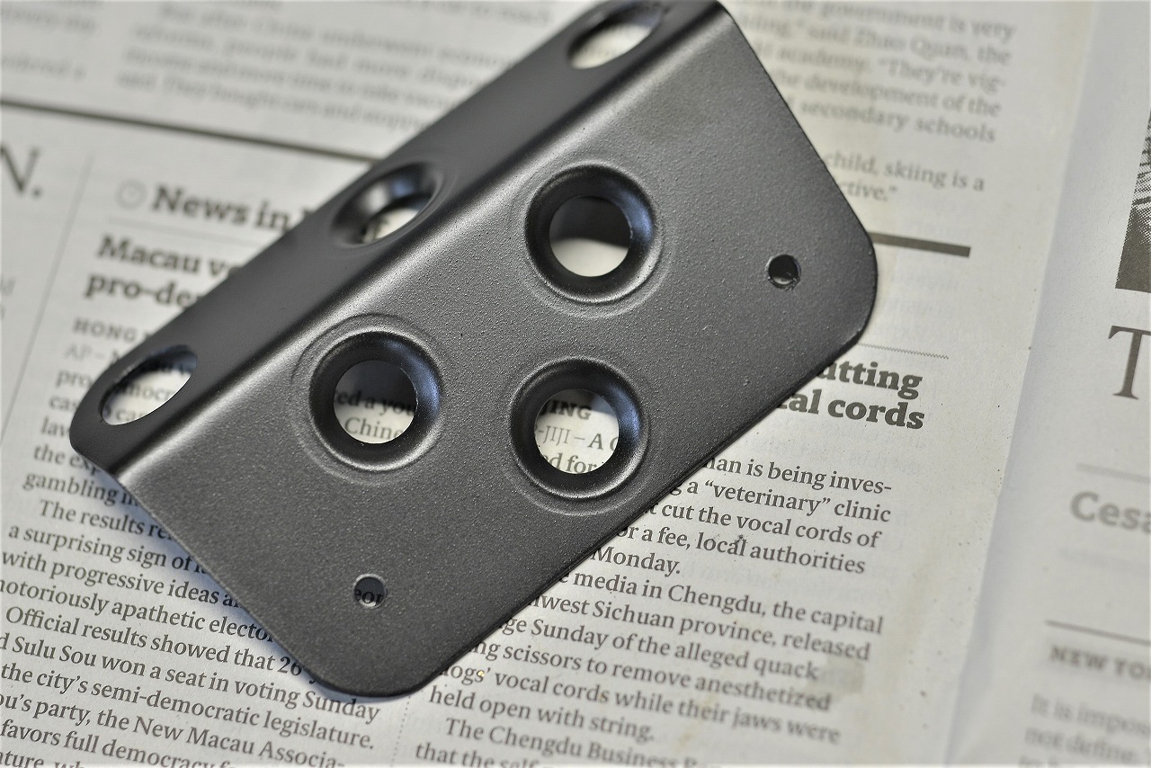
I also gun-coated the base of the key bracket.
Matte black is just perfect.
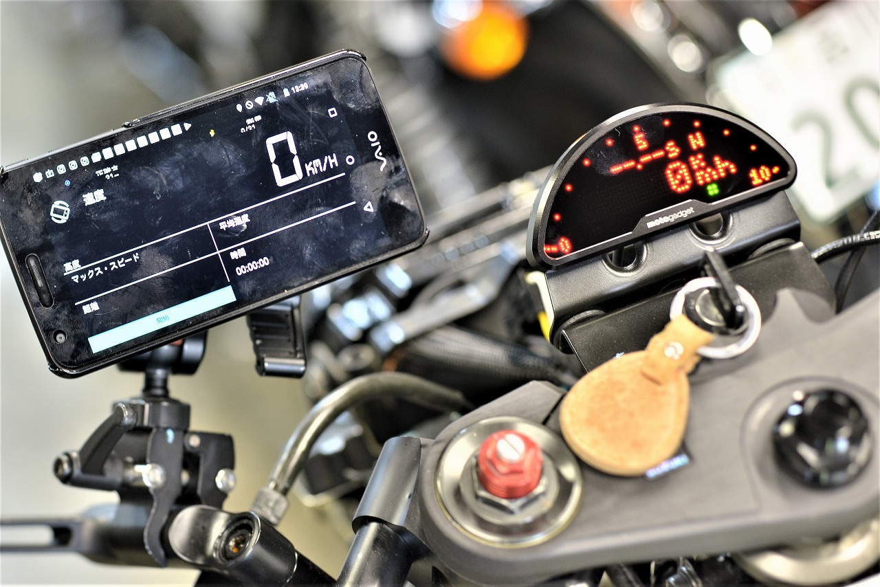
Using my universal mount and the smartphone app “GPS Meter,” I checked the error.
After using it, I think the learning function is more accurate even without entering the tire circumference.
In the old days, the only way was to run alongside and have someone honk the horn at a certain speed…
I’m grateful.
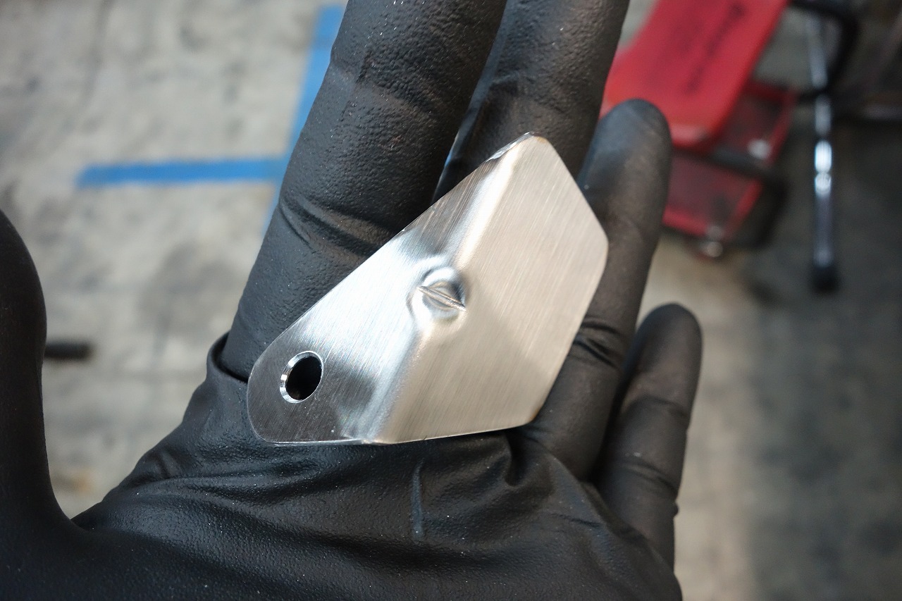
The ETC bracket was a bit wobbly, so I remade it. (With ribs)
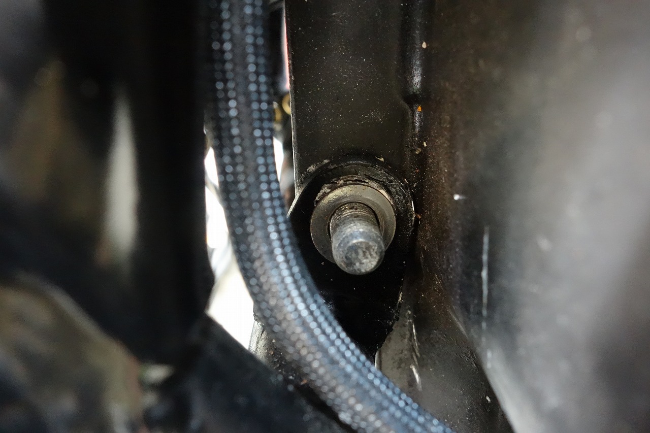
I was laying out the signal generator and noticed there was no nut, so I added one.
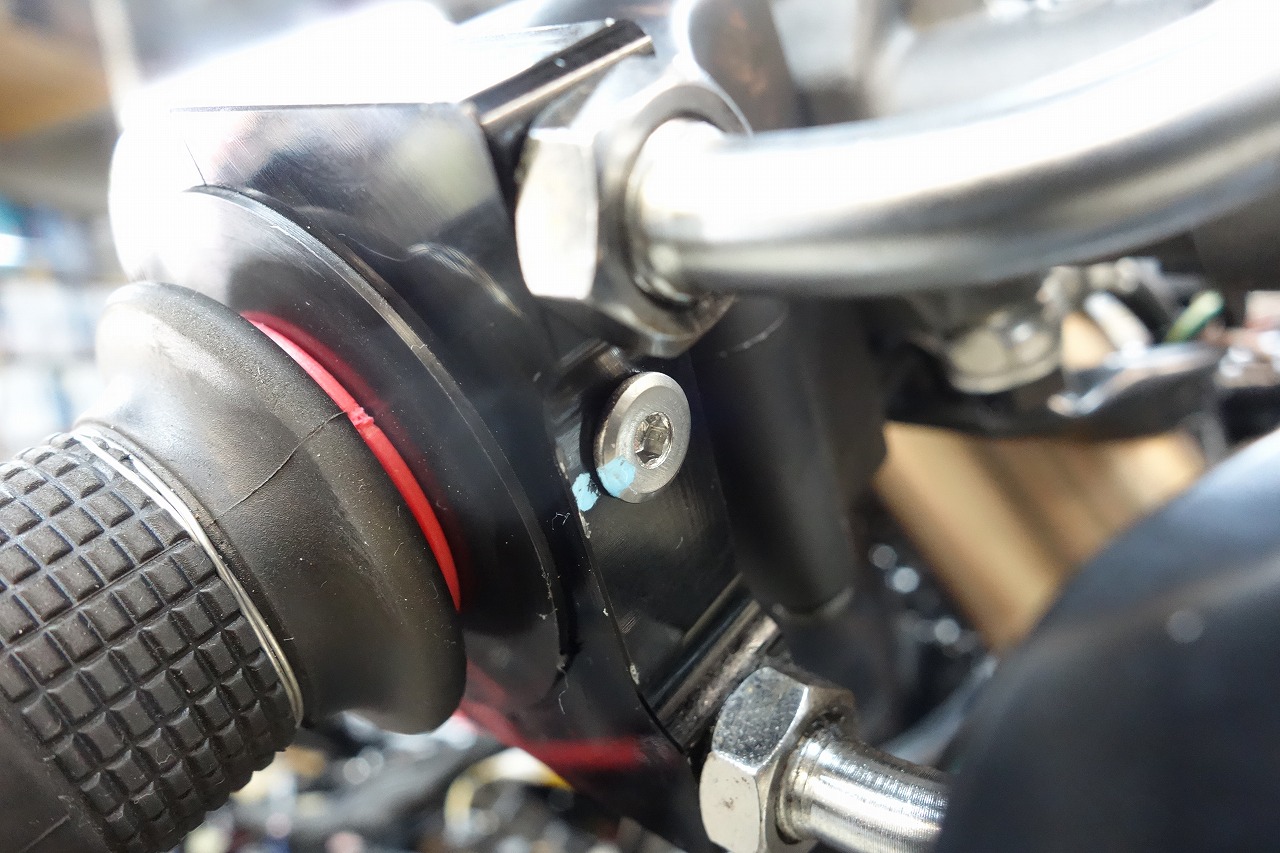
The throttle was changed but there was no stopper, so I added one.
Aftermarket throttles come with a stopper bolt.
When the throttle is off, it should “click” to make contact, and you adjust the throttle cable tension accordingly.
*Without this, you’re adjusting by “pull and return balance.” It results in a really weird throttle feel.
With the throttle off, it goes “mushy…” The return is also too tight, making the throttle a bit heavy. If you have an aftermarket throttle, you might want to “take a good look” at it once.
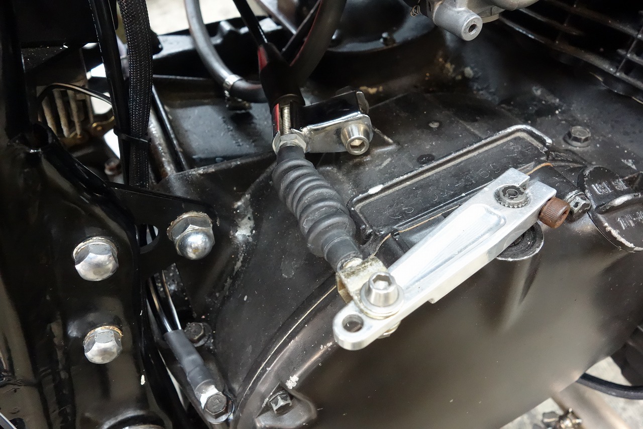
The surprisingly heavy clutch.
I think it’s improved quite a bit.
Almost done. Looking at the blog, it seems quick, but I basically crushed it last week.