Labor and materials, yet people compare it to mass-produced prices—that’s what makes custom work tough.
So here we go!
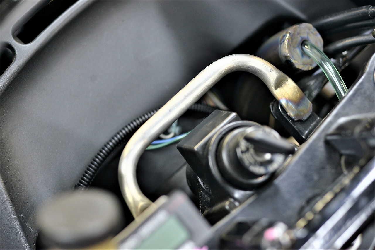
Panel method
Pipe method
I tried the panel approach first, but the distance from the mounting point to the meter was awkwardly spaced—looked terrible (subjective opinion).
The panel became scrap immediately, and I switched to the “pipe method.”
With custom work, keeping things simple rather than tricky is easier on the mind and schedule, so I went with a very straightforward approach.
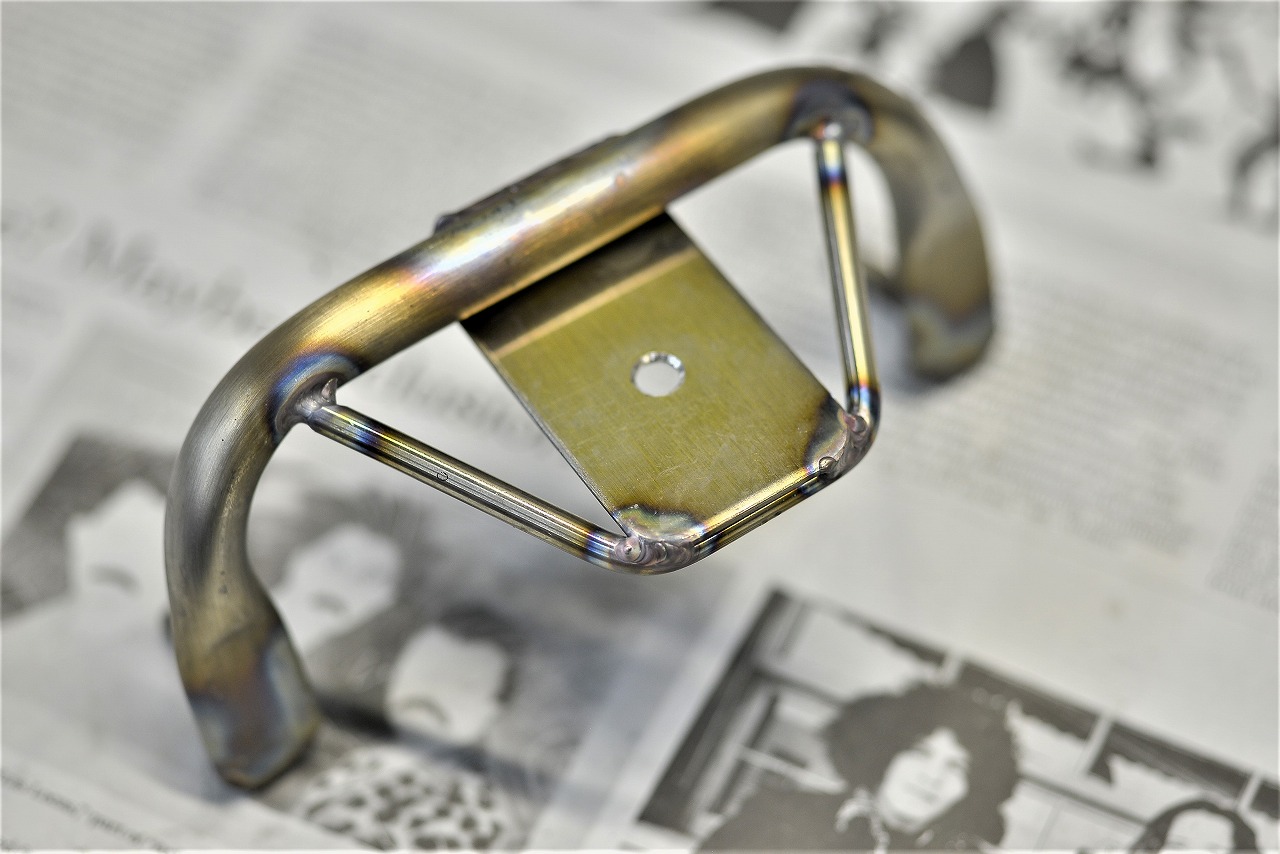
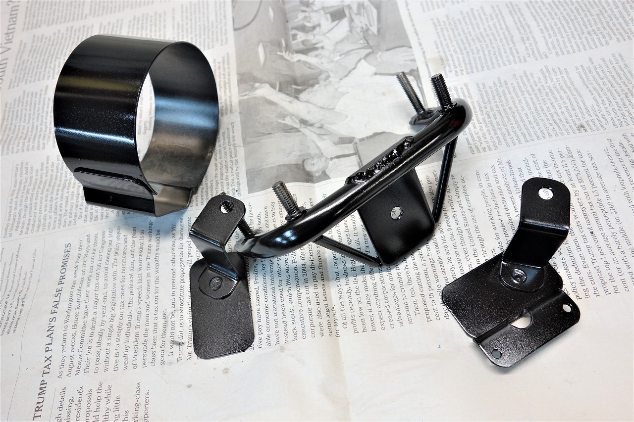
I bent and flattened pipe, then did a low-profile weld to create the base.
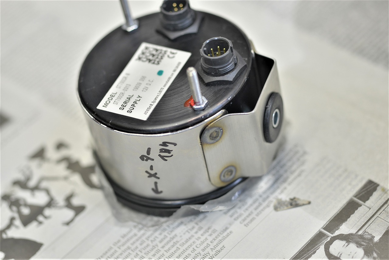
How should I attach it to the base?
Panel
Plate
Clamp
I came up with three options.
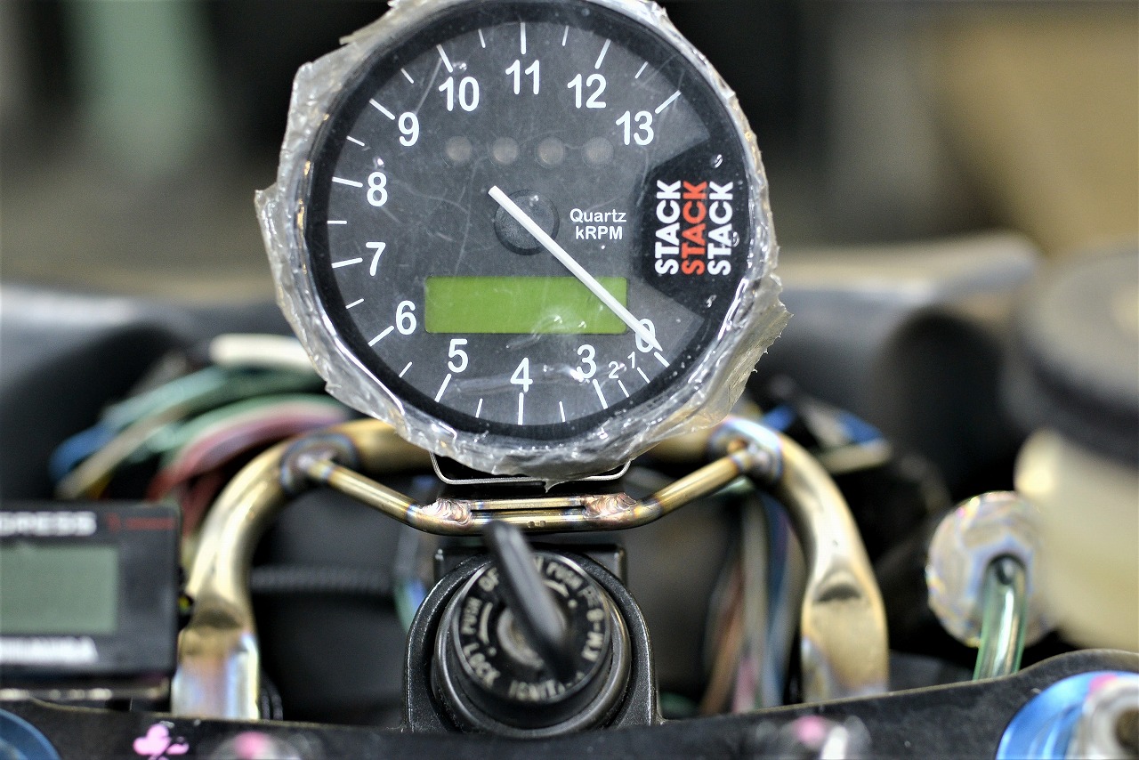
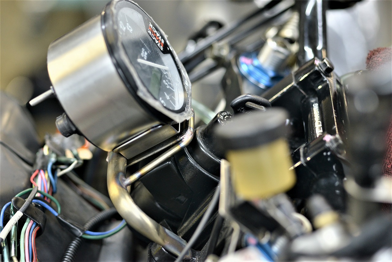
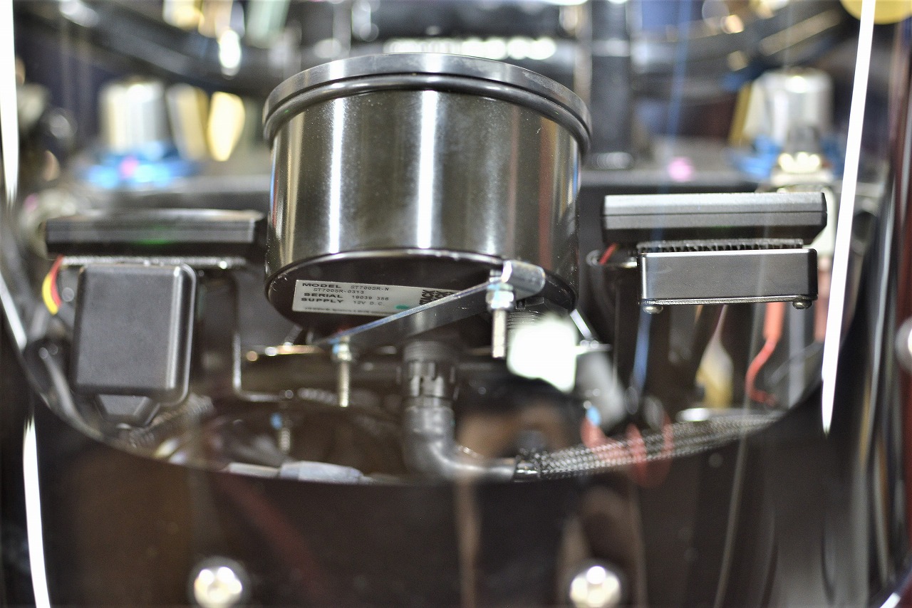
I decided the meter should look like it’s floating with clean, simple mounting, so I chose the “clamp.”
This C-shaped plus convex plate spot-welded together—it’s easy, flexible, and reusable. Three benefits rolled into one.
From my experience installing speedometers:
Front wheel mounting—wiring looks bad and serviceability is poor.
Rear wheel—wiring looks bad, serviceability is poor, and you have to account for chain adjustment. If you mount it to a support, there’s a risk of damaging the sensor when removing the wheel.
So when possible, I’ve been picking up the signal from the front sprocket lately. (I haven’t installed that many meters, and it’s not something I welcome as a job, so I usually decline.)
Good serviceability
Good appearance (clean wiring)
Less risk of sensor damage during maintenance
More pulses captured—smoother needle movement and fewer errors
If someone wants to change the final drive ratio, I’d use an elongated hole design. Or you could decide first, then install.
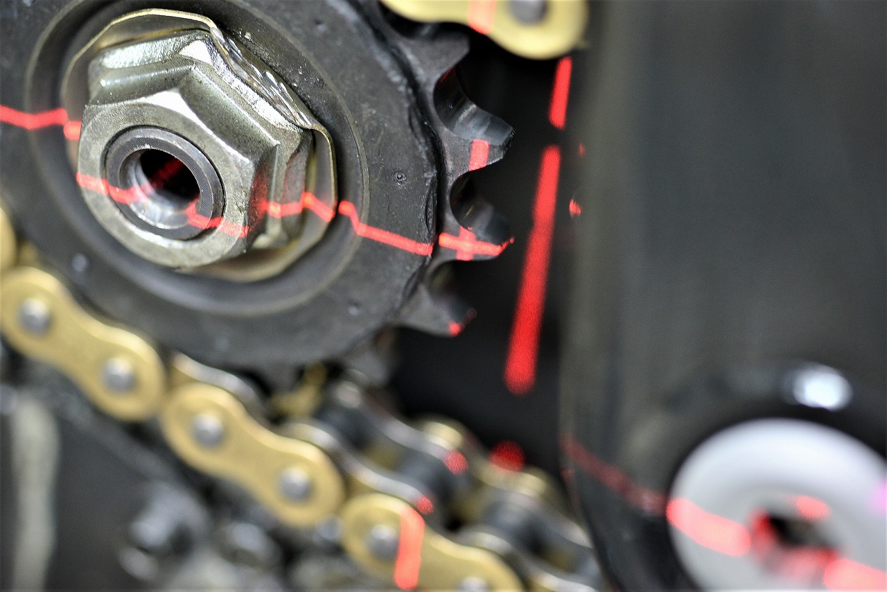
I use a laser to mark where the sprocket teeth come, put a cover on it, and mark about five spots with a marker.
The goal is to find a spot that’s easy to machine and won’t cause installation problems—somewhere with clearance.
When you need to drill a hole on the outside relative to an inner position, a laser is really useful, so give it a try.
Huepar 2-Line Red Laser Level—Red Cross-Line Laser with Auto-Leveling, High Brightness, 130° and 150° Line Emission Angles, Compact.
Something like this is plenty.
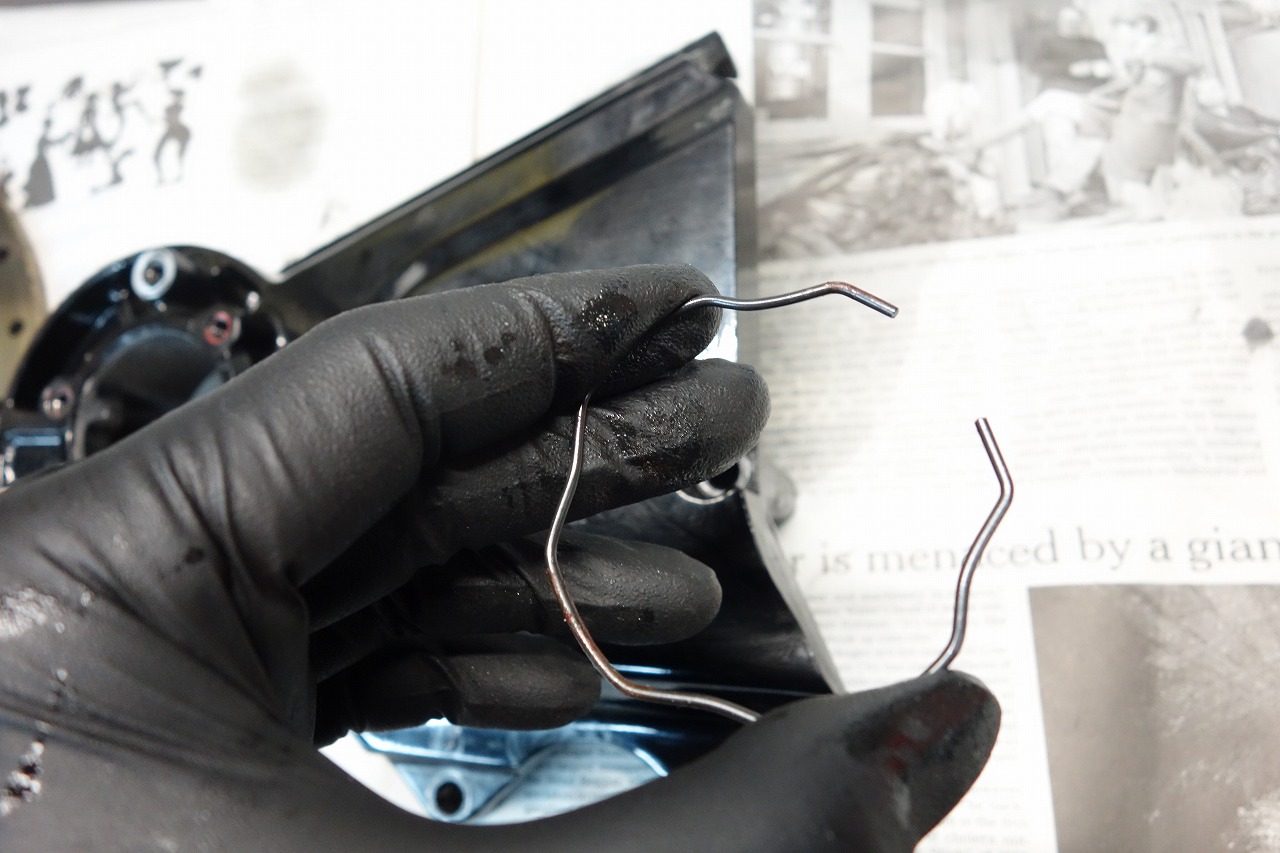
I’m double-checking that the five spots I marked on the outside and the position on the back are okay.
The snap ring… seems fine. Probably. That’s how we’re moving forward.
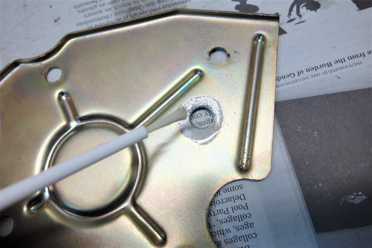
When you want to remove plating before welding, solder flux actually works pretty well. (But you need to wash thoroughly afterward, or it’ll rust like crazy—be careful.)

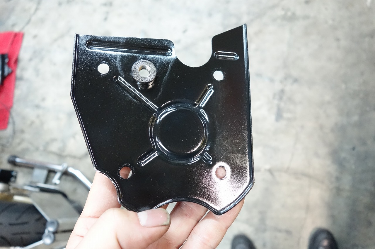
The weight was misleading, so the speed sensor is M8-P1.00. I machined an iron boss, cut threads, and welded it.
Double nuts are a pain to adjust—this way is easier on me.
If you’re going to paint something, I really recommend gun coat.
Single-component—good shelf life
Bake to full cure—saves time
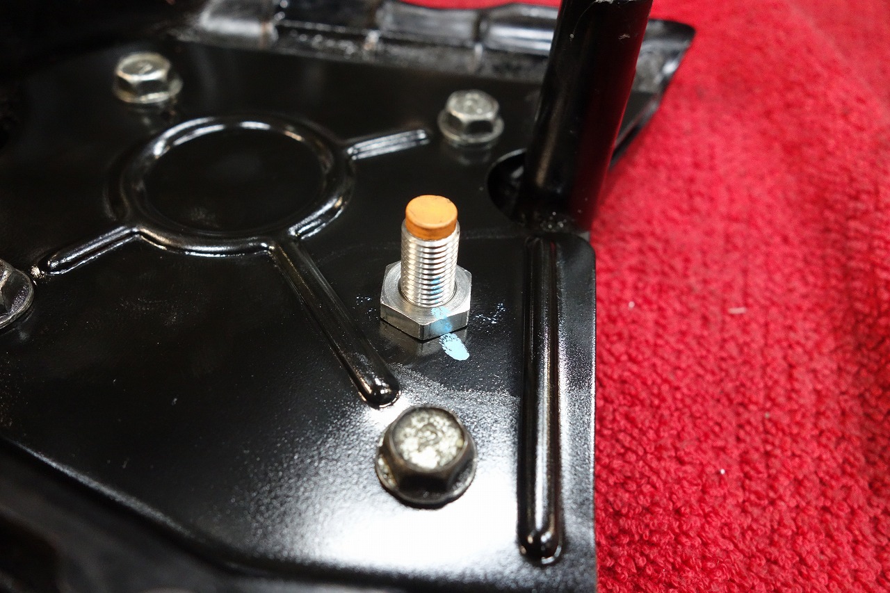
Though “calculated” is a generous term—I used the primitive method of pushing until it touches, then backing off. P1.00 means one millimeter per revolution.
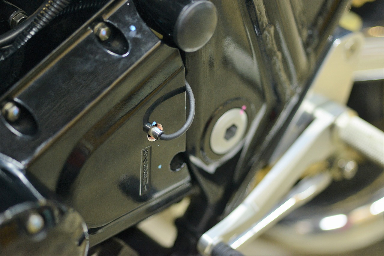
I hope you can appreciate how much subtle effort and time this takes.
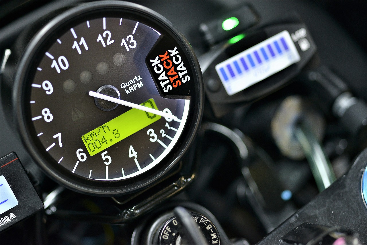
The result looks clean and simple, which I think is excellent.
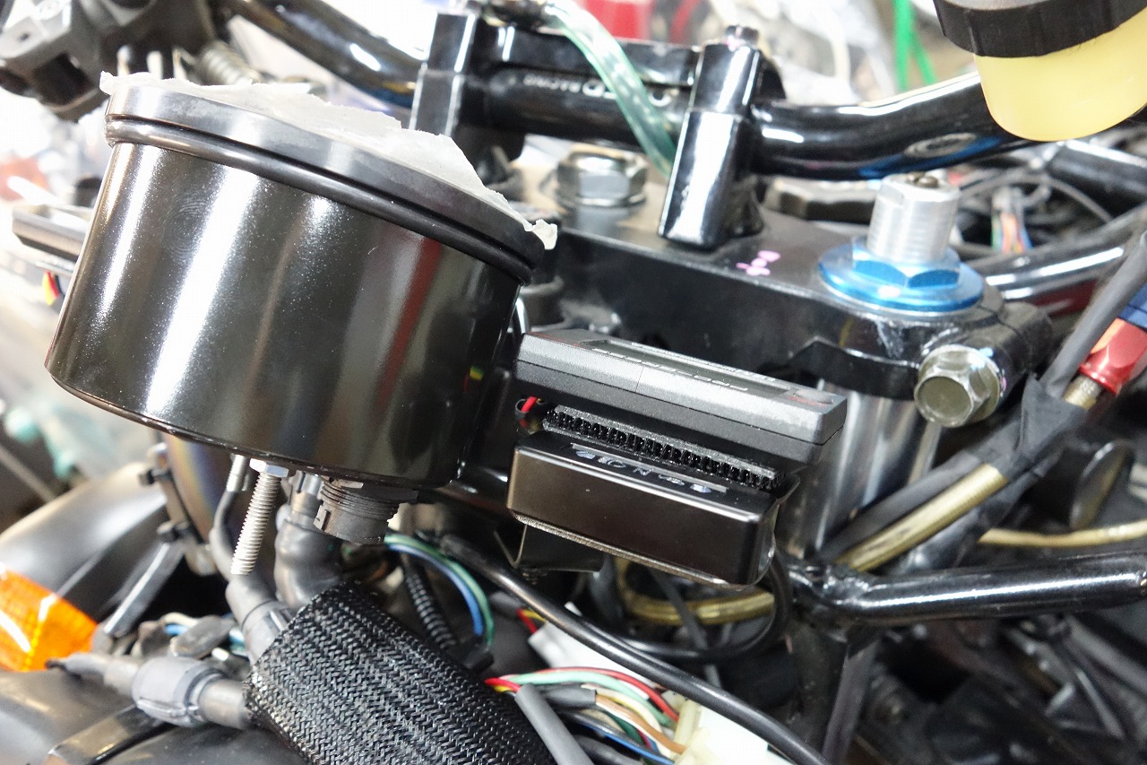
For the indicator: Daytona BETA Micro Indicator Black
Lately, really good products are available at reasonable prices.
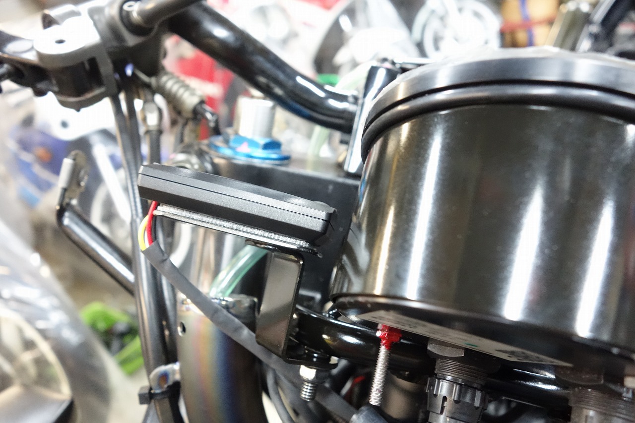
Since you can adjust the settings, it’s very convenient.
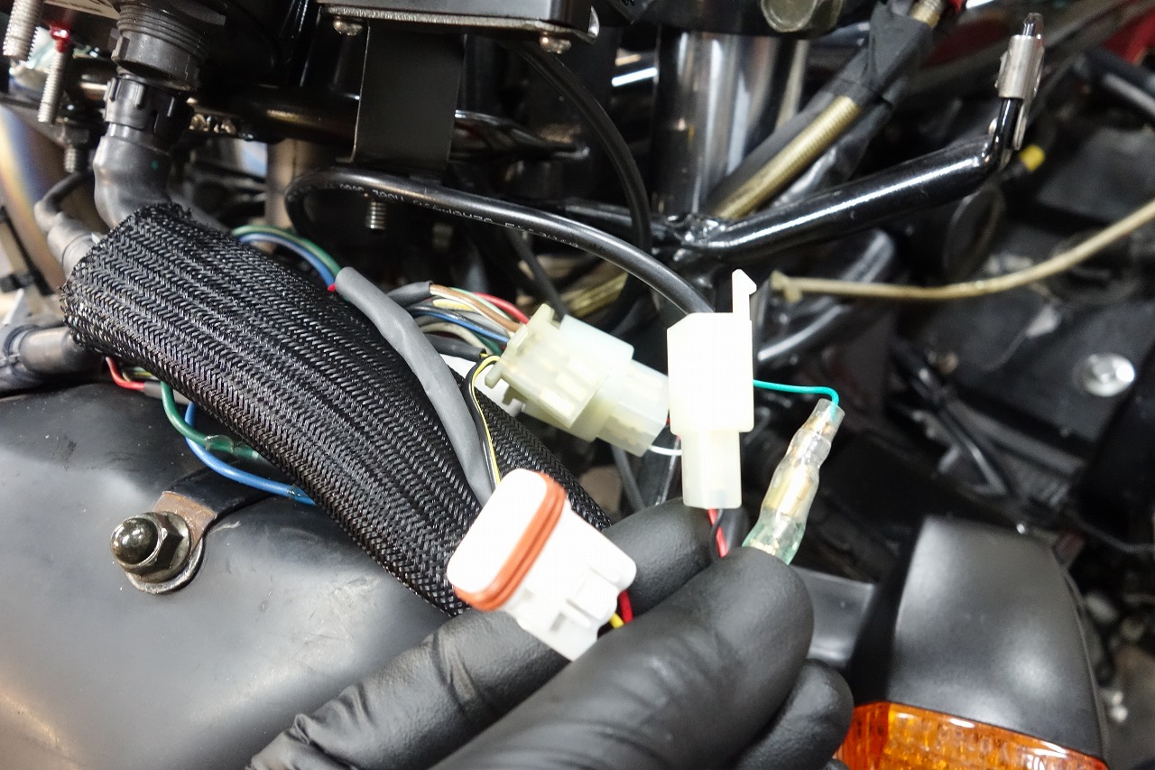
The meter itself should have a quick-disconnect connector (great for serviceability and appearance).
Cut long wires to appropriate lengths after confirming the layout.
Make it clear to anyone looking (it’ll be easier on you later and on others too).
The finished result looks simple, but it’s surprisingly tedious.
There’s no wiring diagram, so I referenced a different Kawasaki model.
Cutting corners always comes back to bite you—that’s a lesson worth remembering.
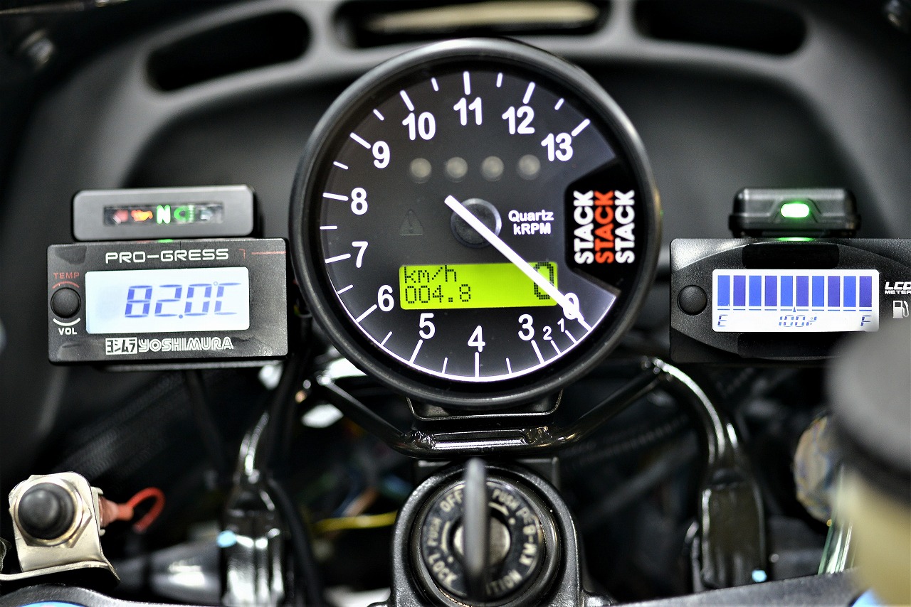
The push button is temporary for now (I want to integrate it into the left switch’s high-beam function eventually).
The rotary switch is only for settings, so it’s temporarily fixed for now (I’ll remove it later).
The digital thermometer is tilted, but it’s flexible, so don’t worry.
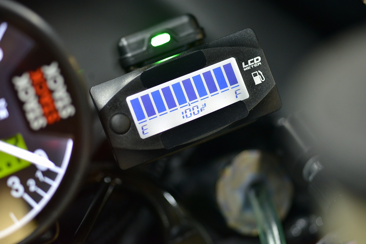
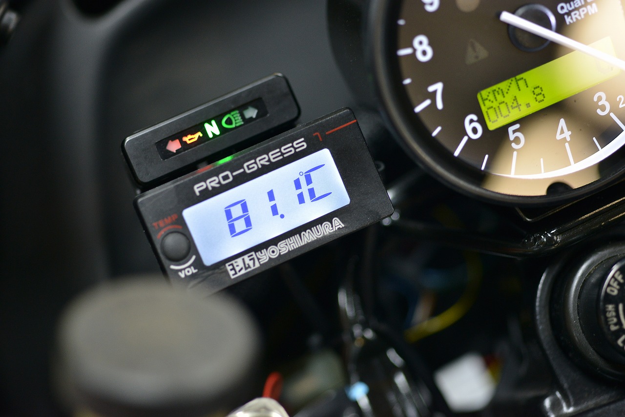
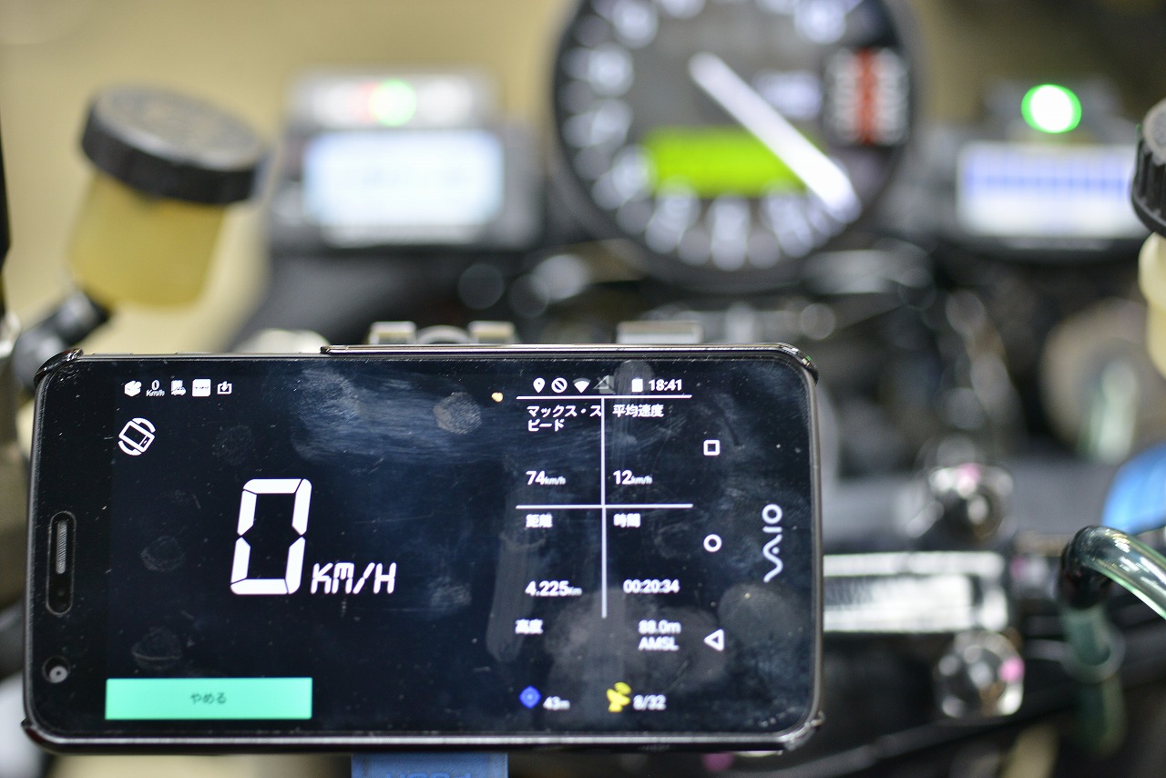
Fine-tuning will happen while riding. That wraps up this work. (´Д`)=3 Phew