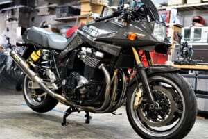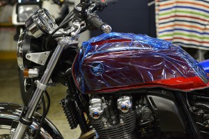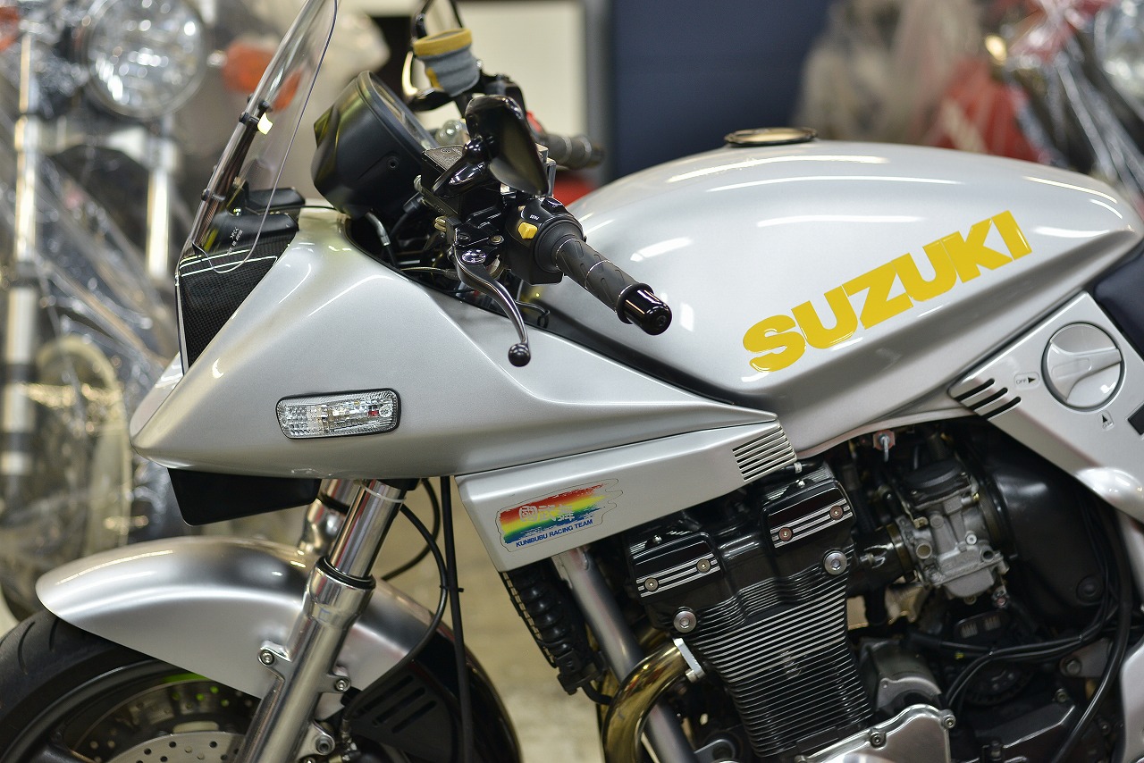
Unicorn Japan GSX1200S oil-cooled Inazuma 1200 Katana
This really is common, isn’t it? I wonder if quite a few of these exist.
It’s truly Katana-like. Originally, I wish the new model had been like this too…
Well, that’s another story.
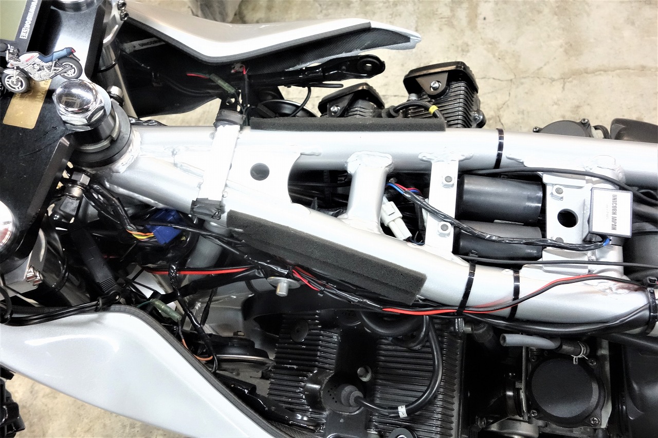
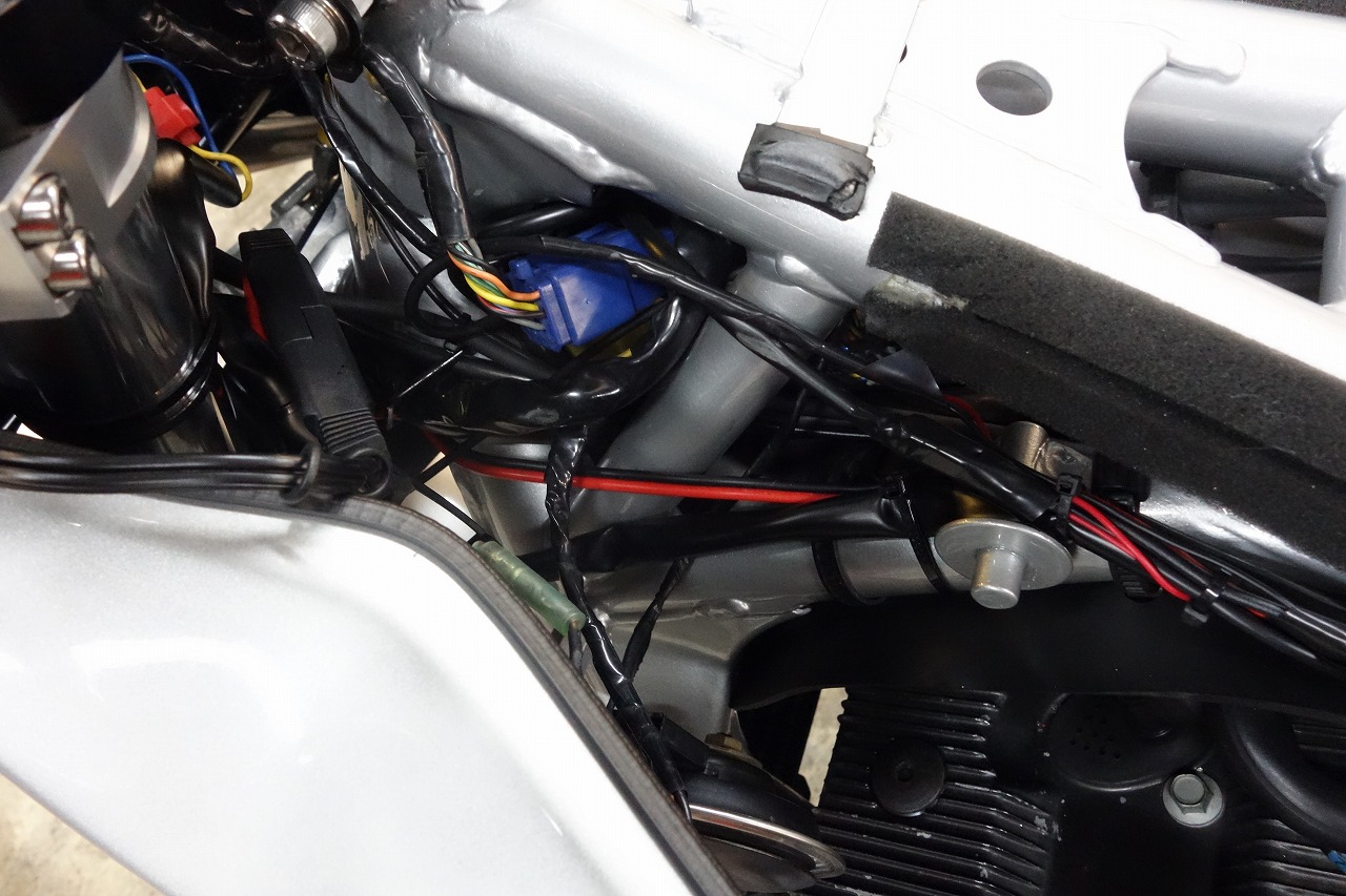
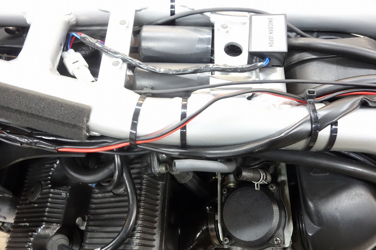
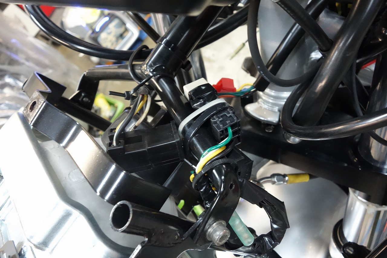
I apologize for doing the wiring as a DIY project at home.
I think it’s unavoidable to some extent when working at home.
There are issues with materials, power supply, and tools.
*For those of you who might request our shop in the future, we’d appreciate it if you didn’t install parts beforehand.
It reduces the work of removing them…
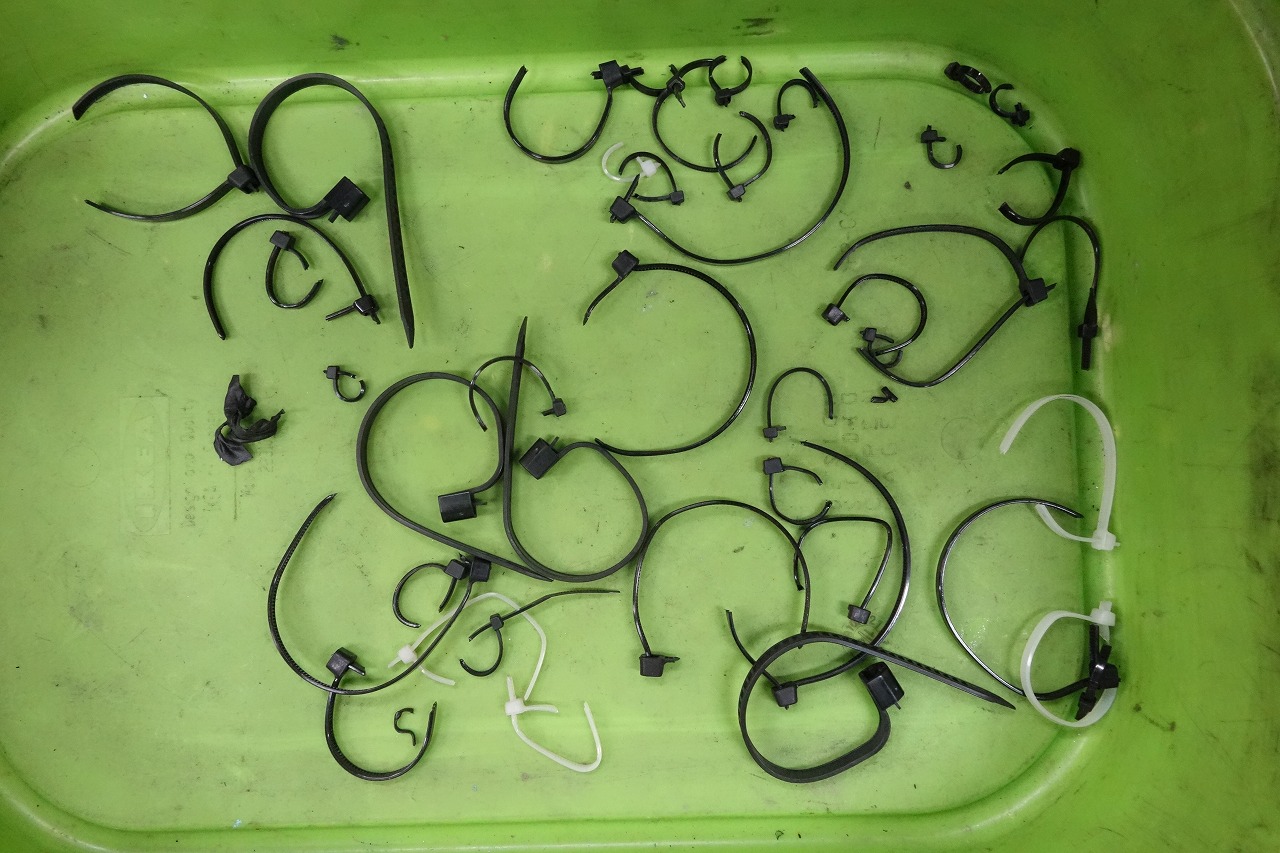
I think it’s good to keep cable ties to around 10 pieces.
Relying on them too much makes installation anything goes.
By limiting the number used, I think you’ll avoid poor layout and forced installations.
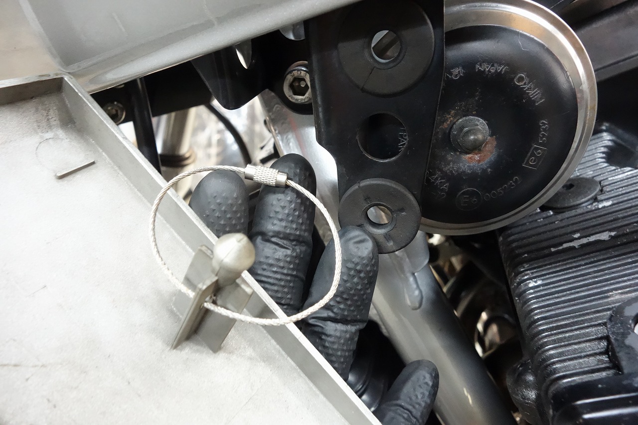
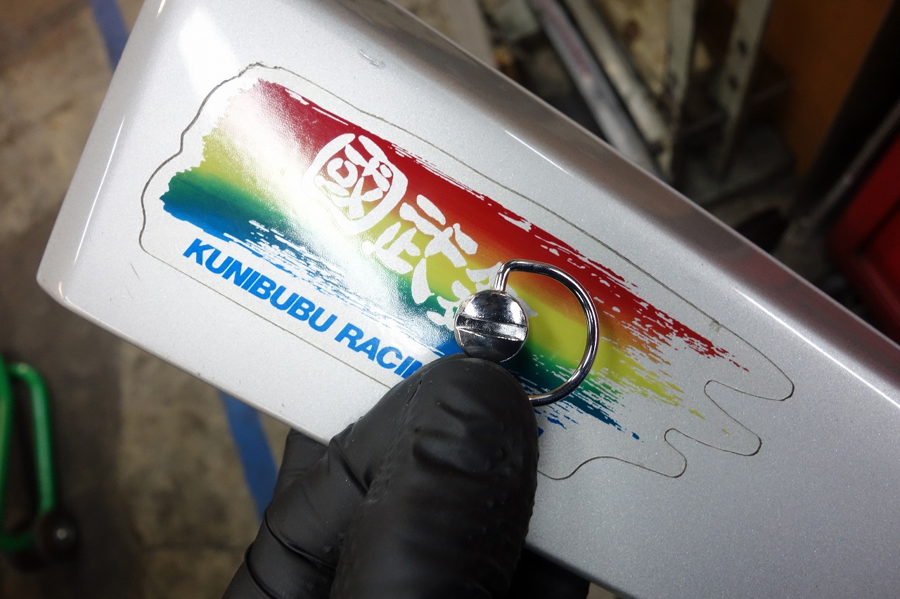
A cover that tends to fall off.
I wonder why so few people use fasteners for this…
What do you specialists think?
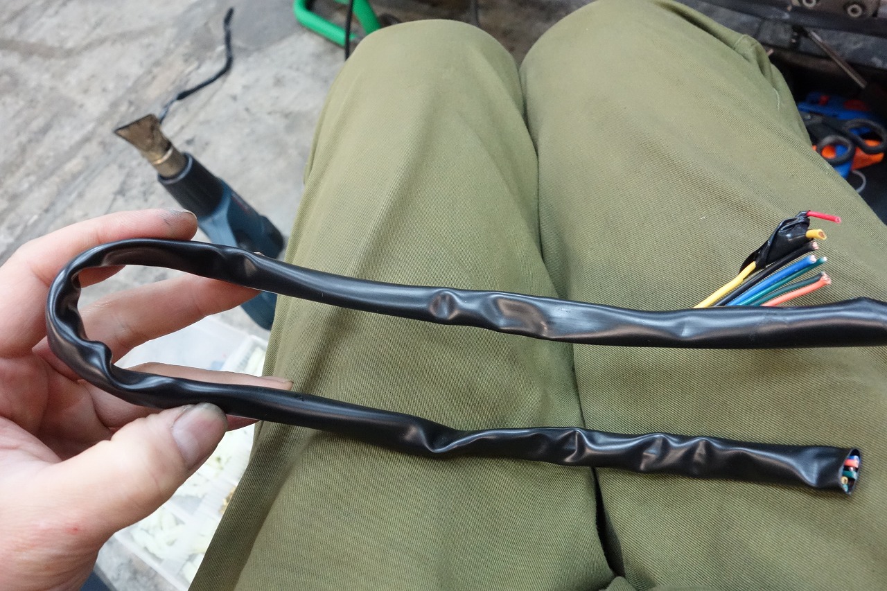
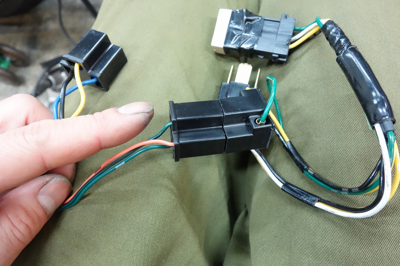
So then… let’s start by reducing the wiring.
• Moto Easy
EASYRIDERS Easy Riders/Moto Easy headlight ON-OFF relay universal
• Daytona headlight relay
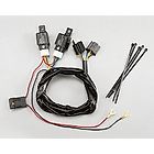
DAYTONA Daytona/headlight relay kit universal
Both are bolt-on designs, so we end up with the annoying H4 connector installation.
The headlight relay picks up the 12V during LO/HI and switches it.
Alternatively, you could get it from the dimmer switch (HI/LO selector) for a cleaner setup.
*Though I don’t do it much myself…
For example, if you make a dimmer clean relay kit…
“It becomes model-specific = hard to sell” — that’s how products are made and sold in this world.
You can install it as-is or modify it for a cleaner look.
*Though modifying it voids the warranty…
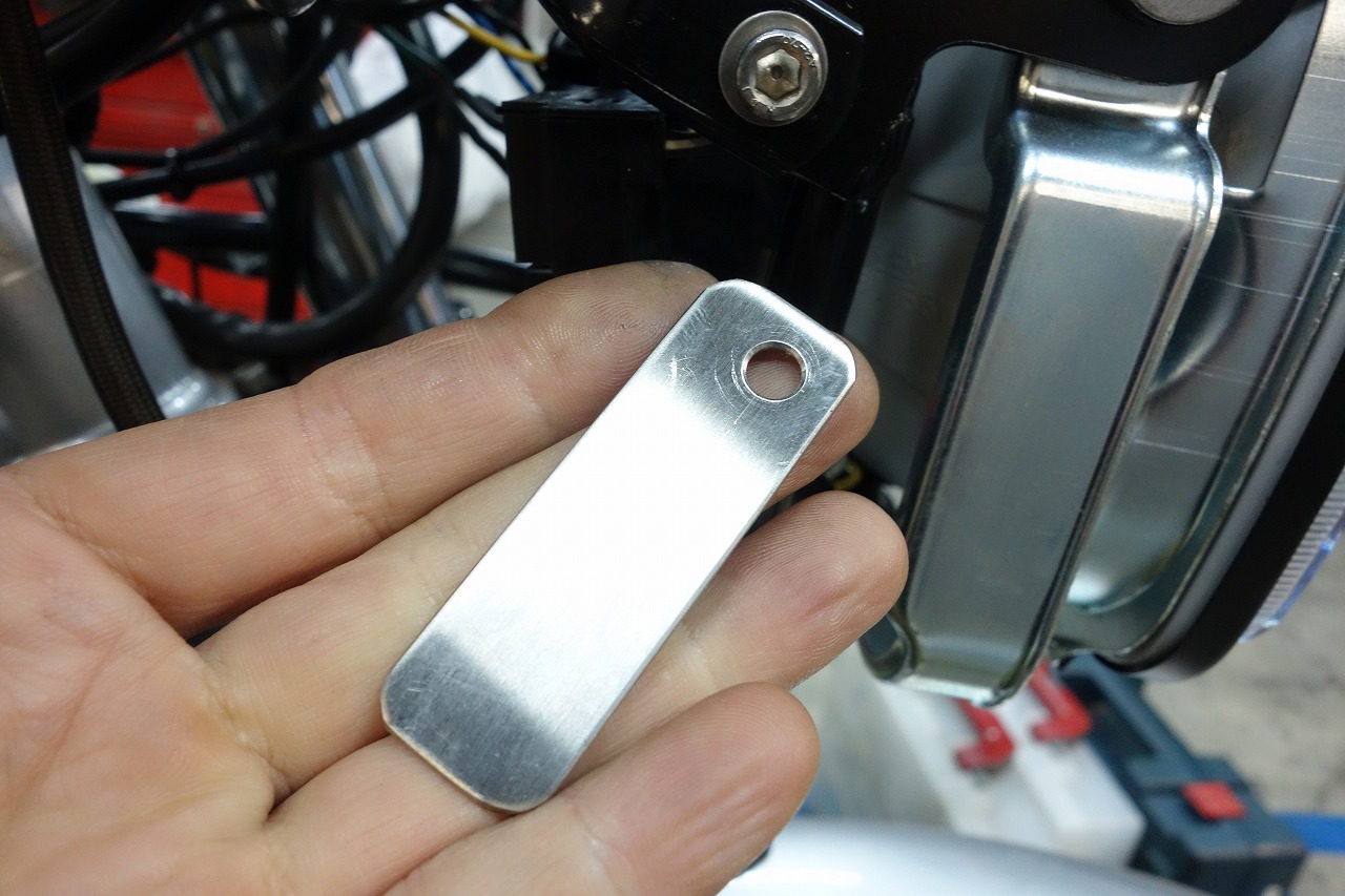
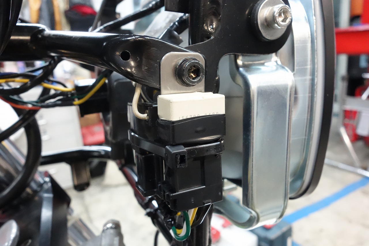
Using cable ties to fix it to the frame means you have to cut them every time.
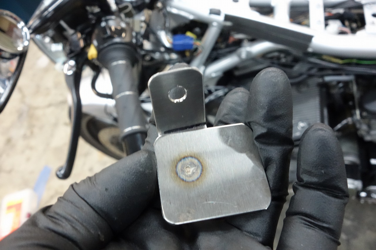
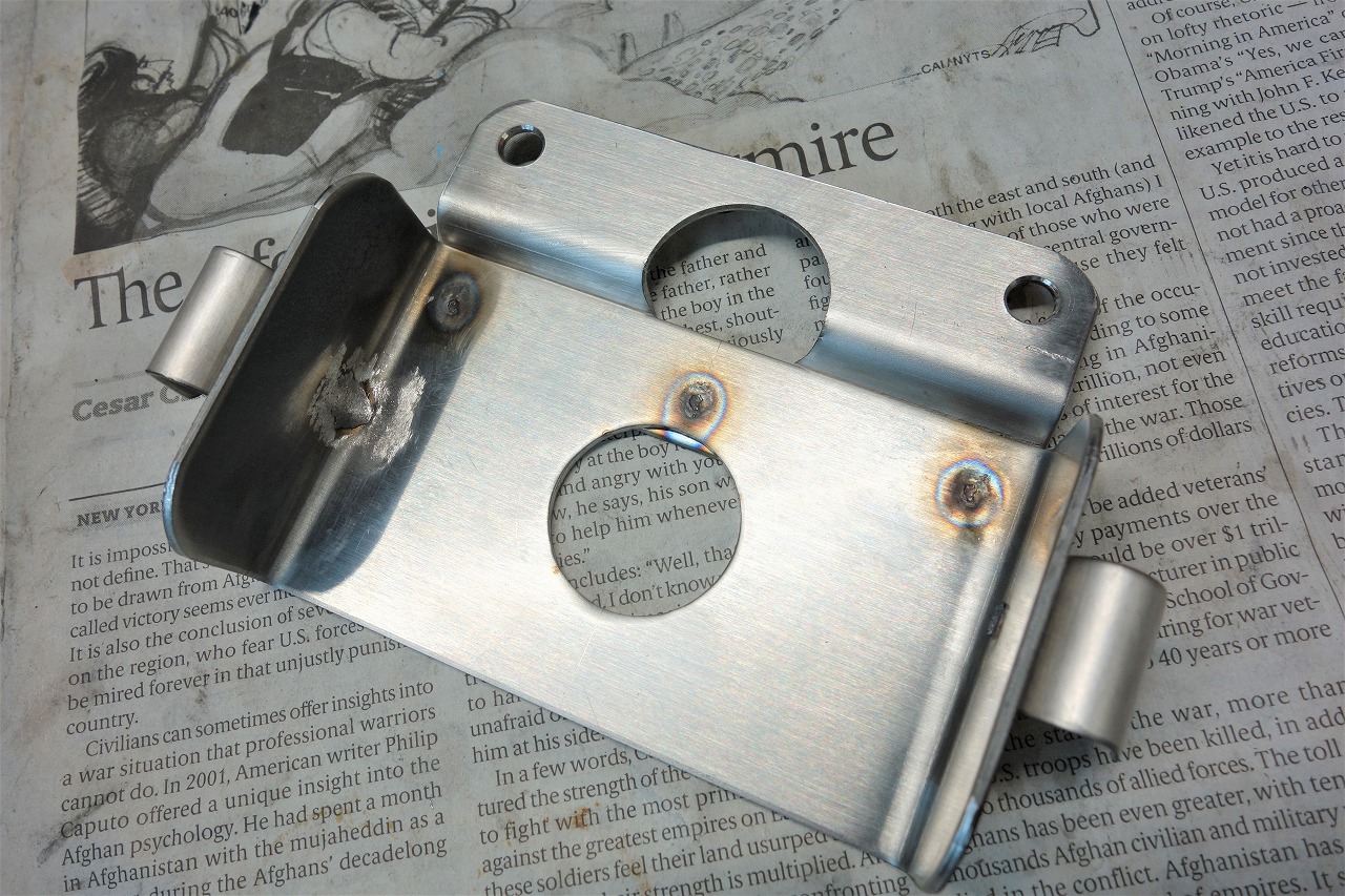
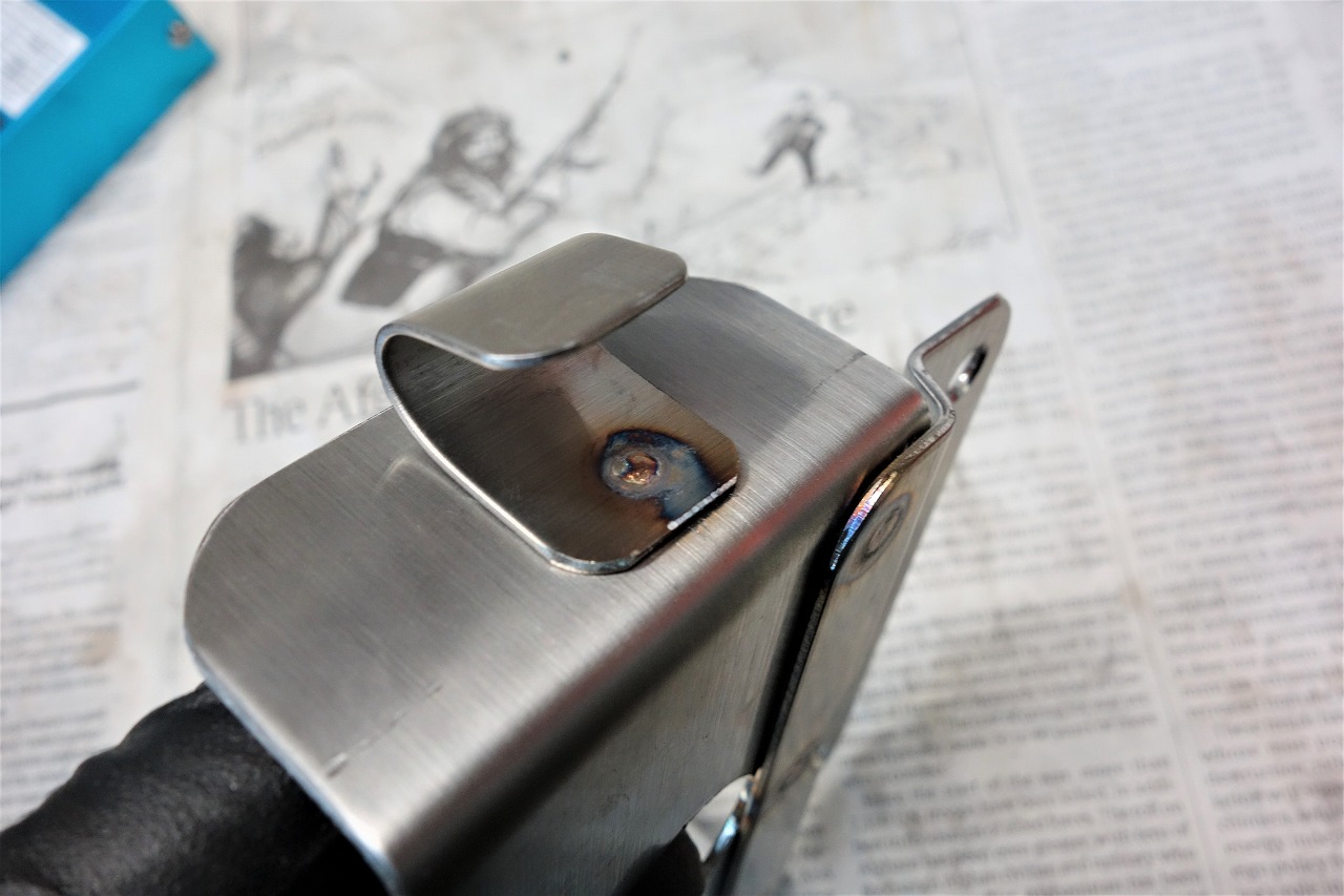
I think it’s worth making a simple plate like this instead of being lazy about it.
You can fix it flush to the surface with cable ties or double-sided tape, and it comes off with one bolt, so maintenance is good too.
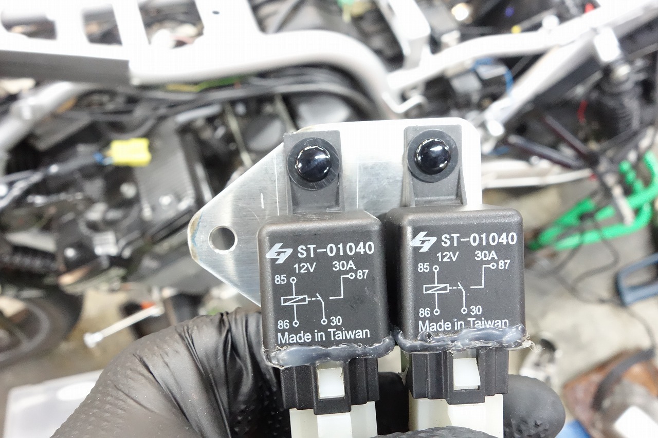
Next.
We’ll also make a plate for the relay and fix it.
Tightening plastic with bolts and nuts feels bad and eventually cracks.
Bolts and lock nuts with loose tightening is an option, but considering weight and convenience, I think push rivets are better for fixing.
And then.
Direct battery relay = attached to battery positive, that’s right.
Want to try a different approach and clean up the battery area?
If you’re thinking “ugh, I don’t want to remove the battery,” then it’s worth considering.
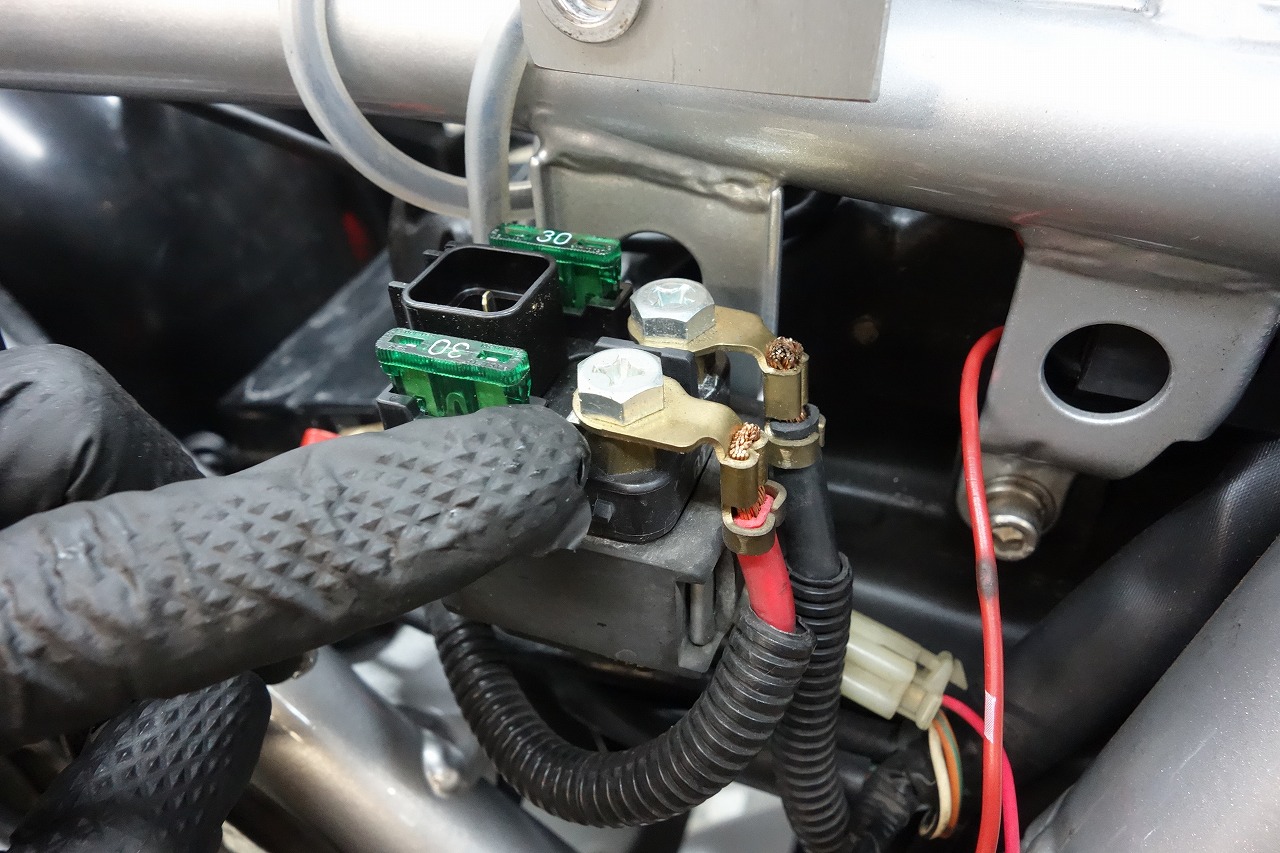
• Get it from the starter relay
The battery positive lead connects to the starter relay. = Battery positive.
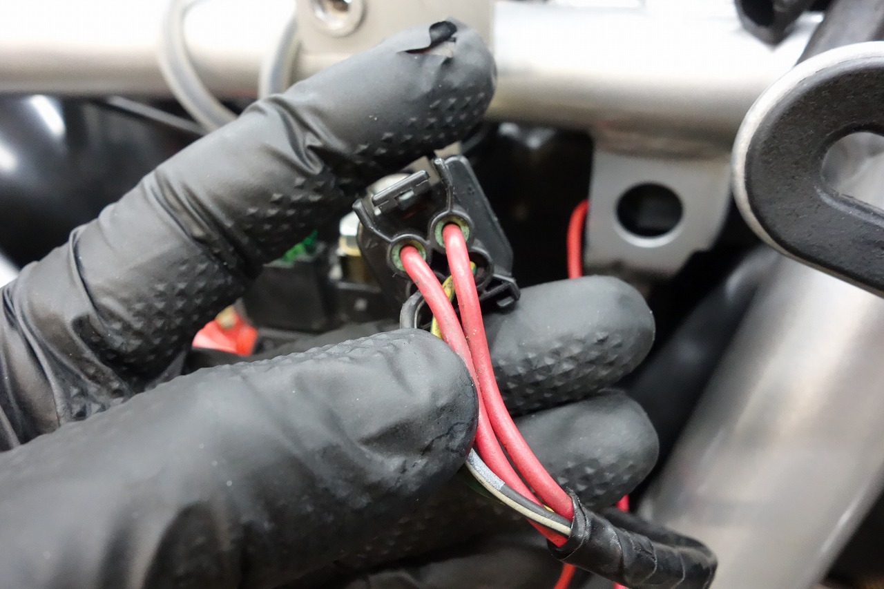
• Get it from main key constant 12V (varies by model)
This requires stripping and modifying wires, but depending on the model, the starter relay has a 30A fuse, so it’s somewhat reassuring.
Like a river’s flow — where do you draw the water from? Where do you build the dam? That’s the question.
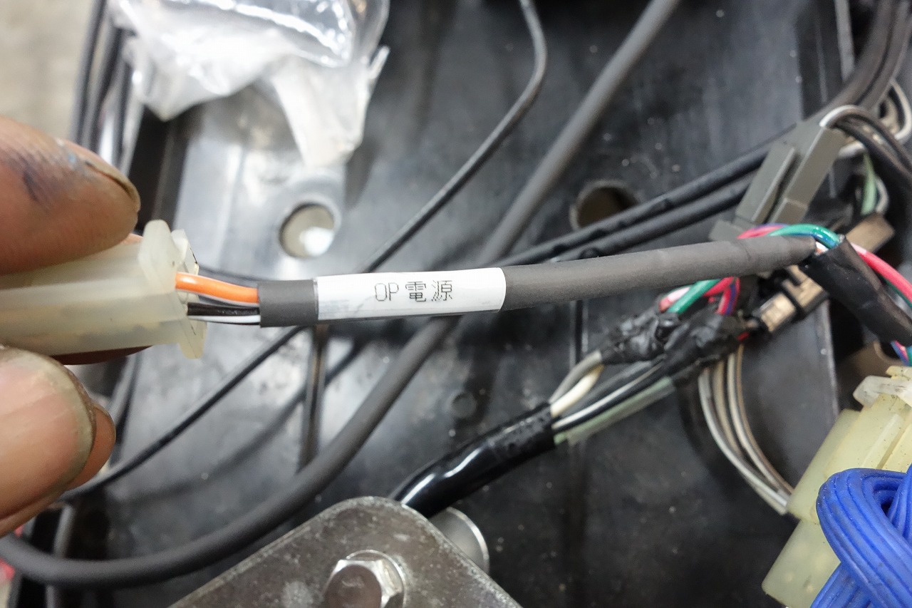
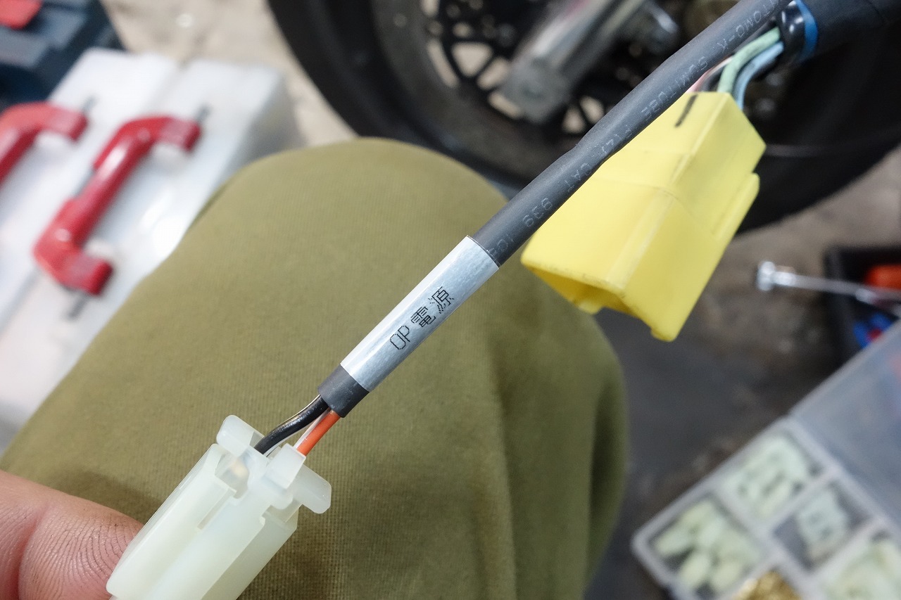
We’ll re-source the ETC power and digital tachometer power.
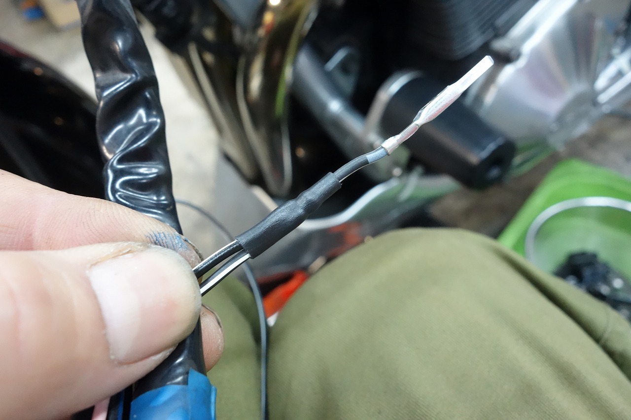
And then and then.
As an easy reference point, look at the wiring diagram
◎ Find a spot where ON 12V and ground are available in parallel
I think that’s the way to go. Bikes with constant headlight ON are really appreciated.
The rear has license plate light and tail lamp, so there’s not much to worry about.
This time we did:
• Left switch (the usual optional power method) = digital tachometer
• Tail lamp = ETC
It’s good to mark the added power sources. (Prevents mistakes and improves future maintenance.)
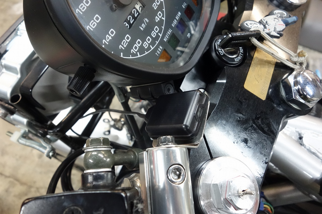
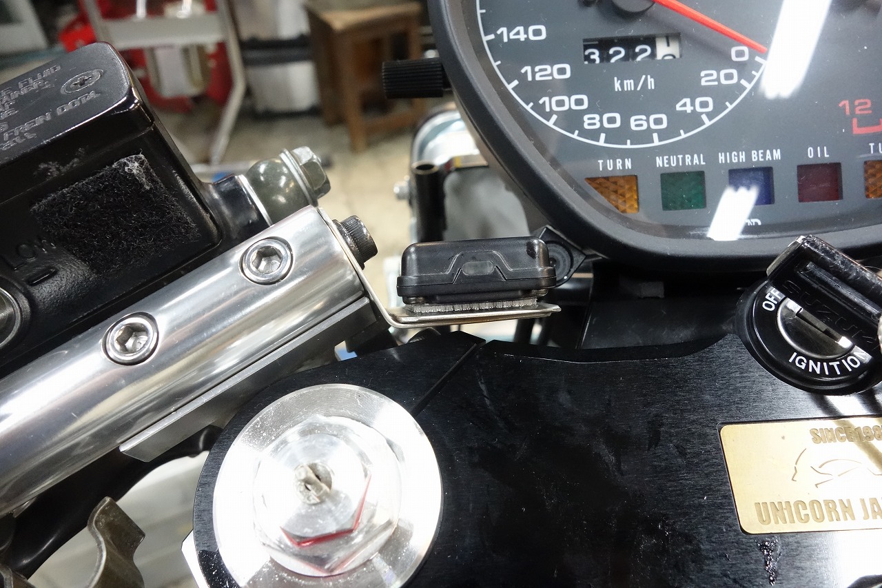
Removing the upper cowl would be a hassle, so we relocated the ETC antenna.
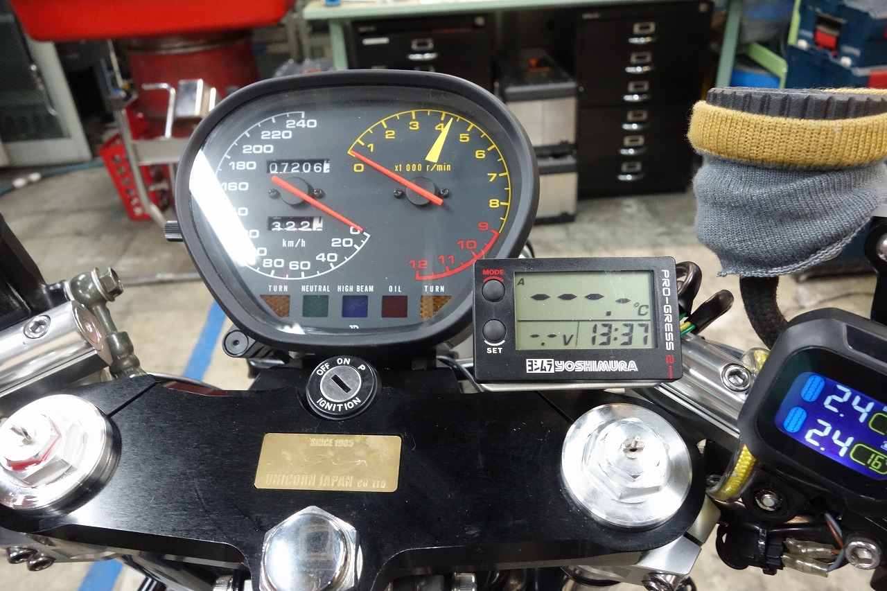
We also relocated the digital tachometer here.
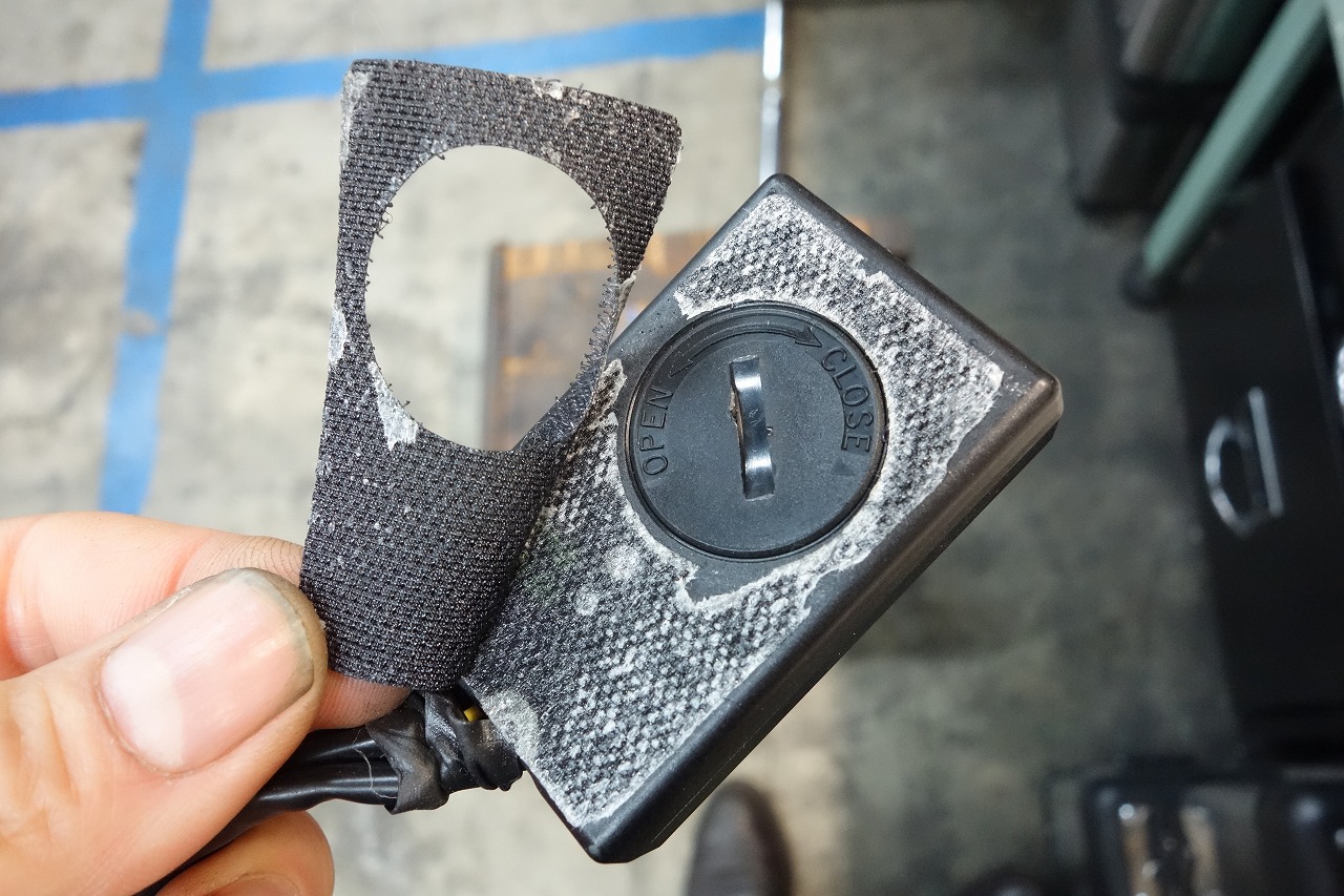
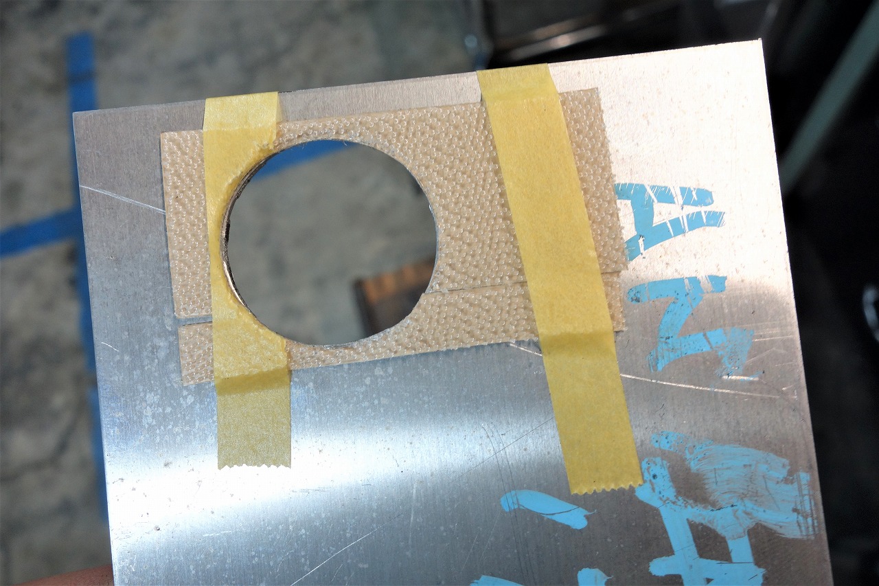
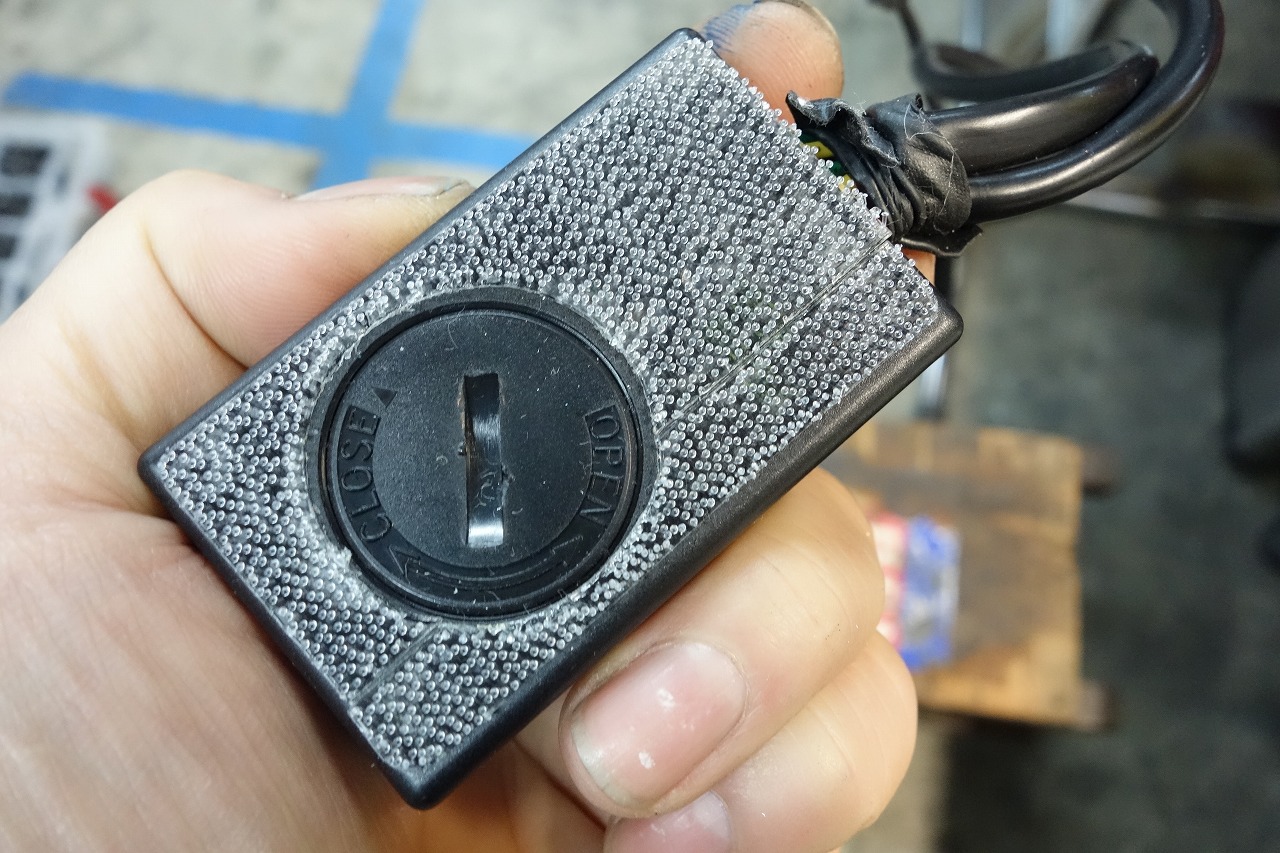
Isn’t the included Velcro weak? It peels off right away…
3M Dual Lock thin fastener SJ-4570 I usually swap it out.
The battery stays secure and hidden — care in the invisible places, that’s nice.
Quietly satisfied.
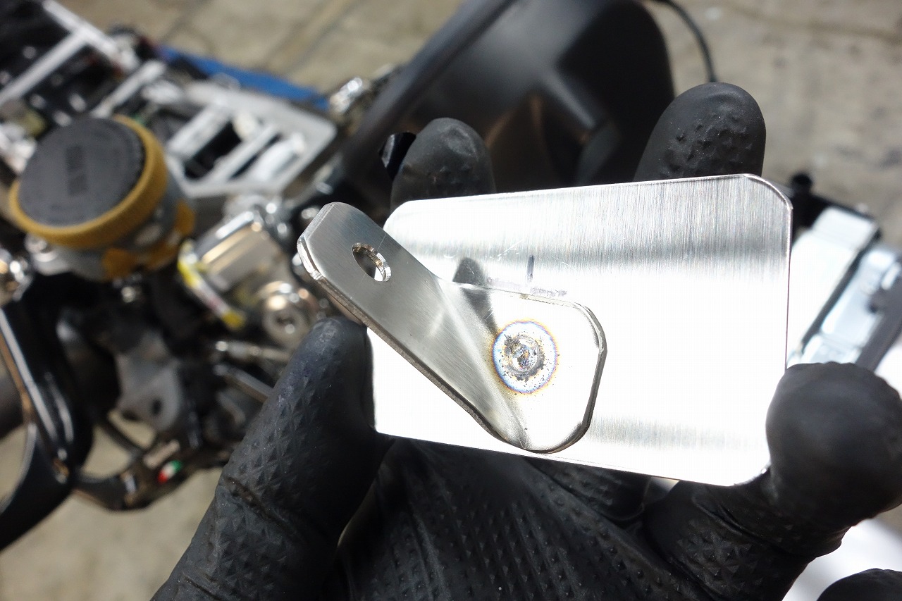
With a spot welder, you can make brackets like this.
Plus, there’s less failure.
Bike shops, seriously! I recommend it! There’s no point doing all this with TIG welding.
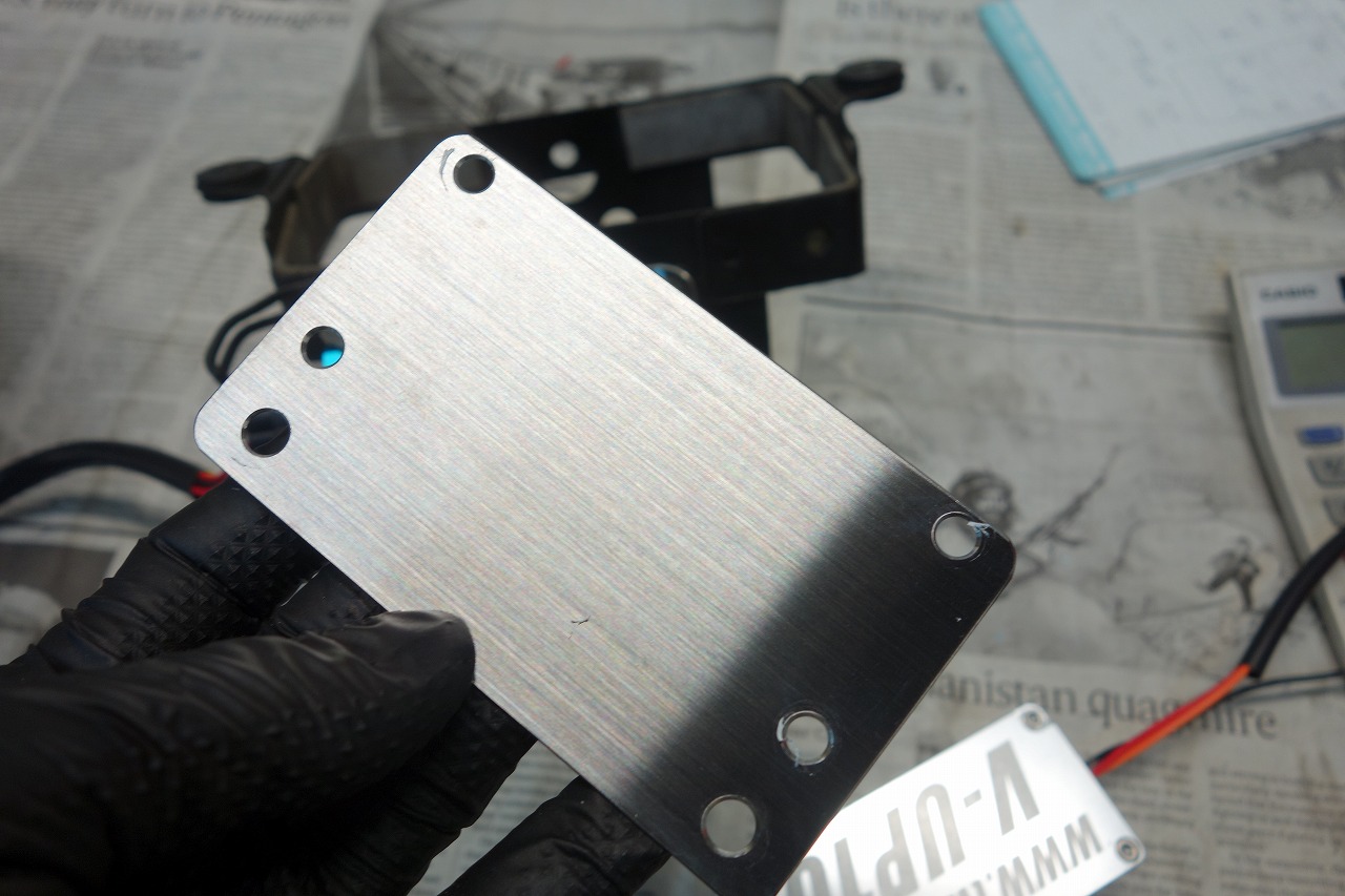
We’re installing the AS Watanabe SP2 and V-UP step-up kit, but…
There’s just no space. The Inazuma 1200 is tough.
We did A+B+C and somehow managed.
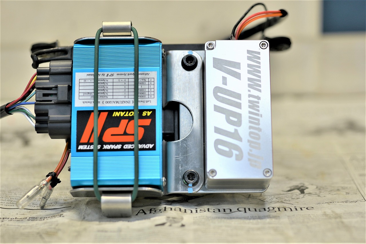
We mounted it to the battery case like this.
It’s almost stock-looking = poor maintenance access, but there’s no choice. There’s really nowhere else to put it.
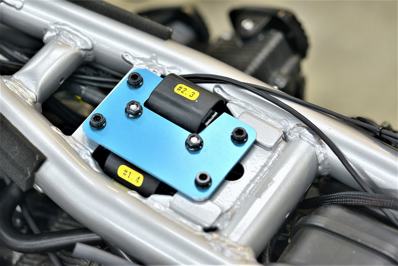
Unusually, we used the included bracket. It would’ve ended up the same shape anyway.
The bracket I made before seems to have been upgraded… I feel a bit defeated.
If only this Watanabe bracket had rounded corners instead of sharp ones…
How about it?
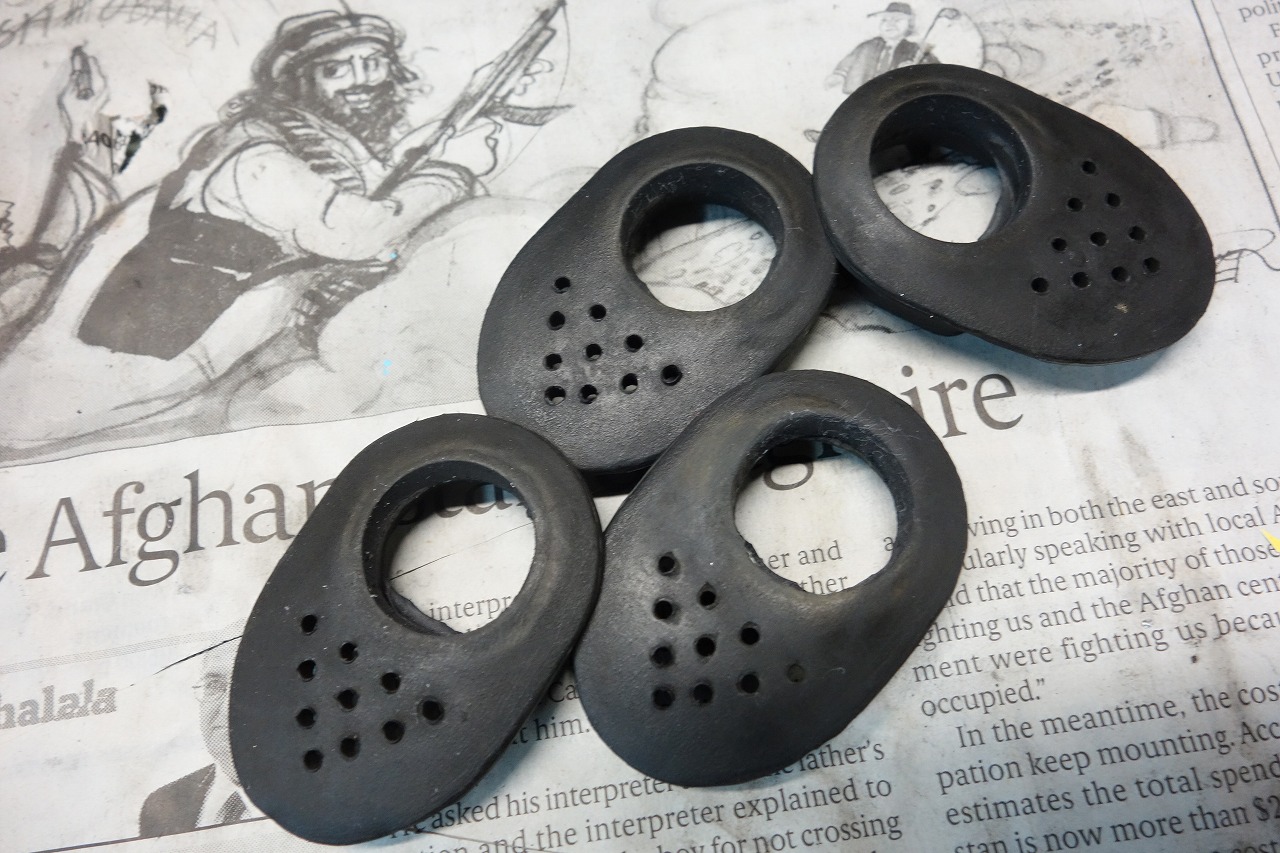
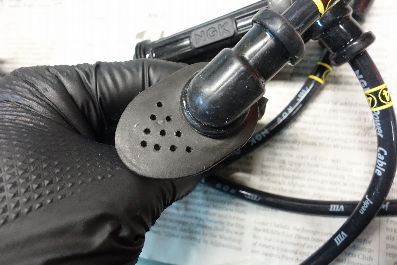
NGK Power Cable X4K 102 degrees
We remove the plug cover with a 20mm packing punch, magazine, and vise.
What we’re doing is no different from what everyone else does.
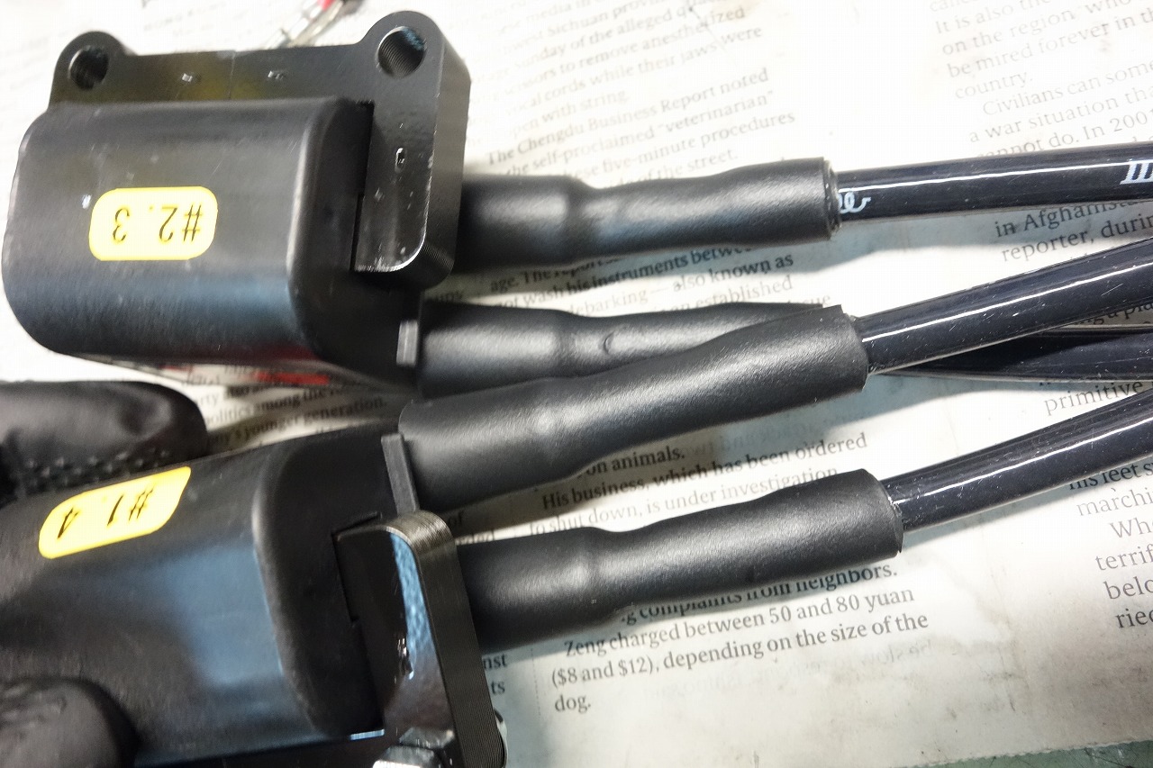
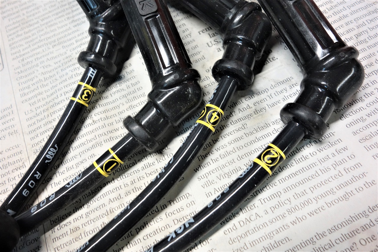
Insert the cord and cover with Denka Electron Yonichi
*We’re using Yonichi double.
• Shrinks to 1/4, so wall thickness increases. Prevents leakage.
• Adhesive melts out for complete waterproof sealing.
The included rubber cover has popped off before, so for safety I’ll never use it again.
If you need to swap the cord, just cut it with a knife.
Considering the risk, complete sealing is better.
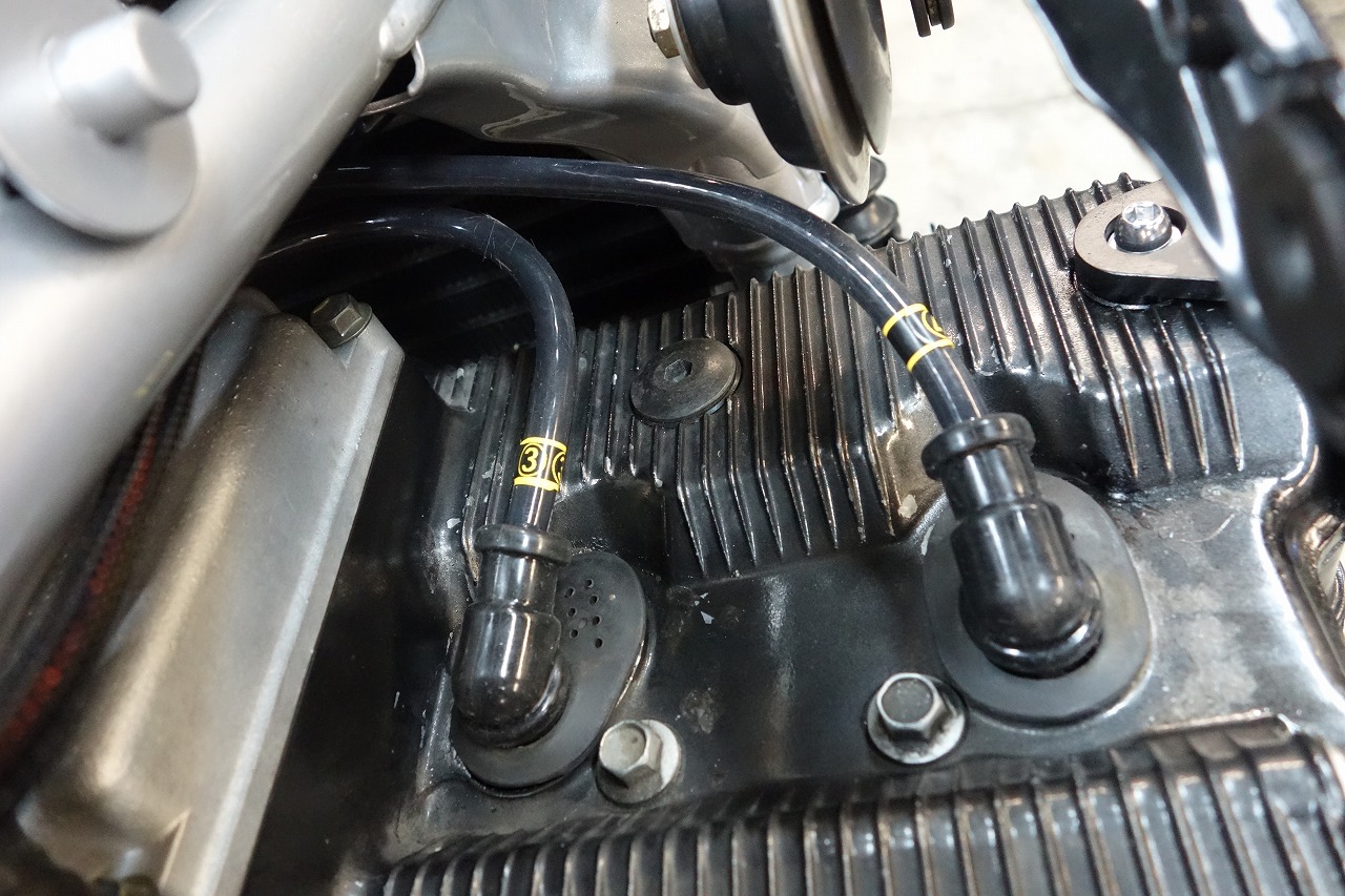
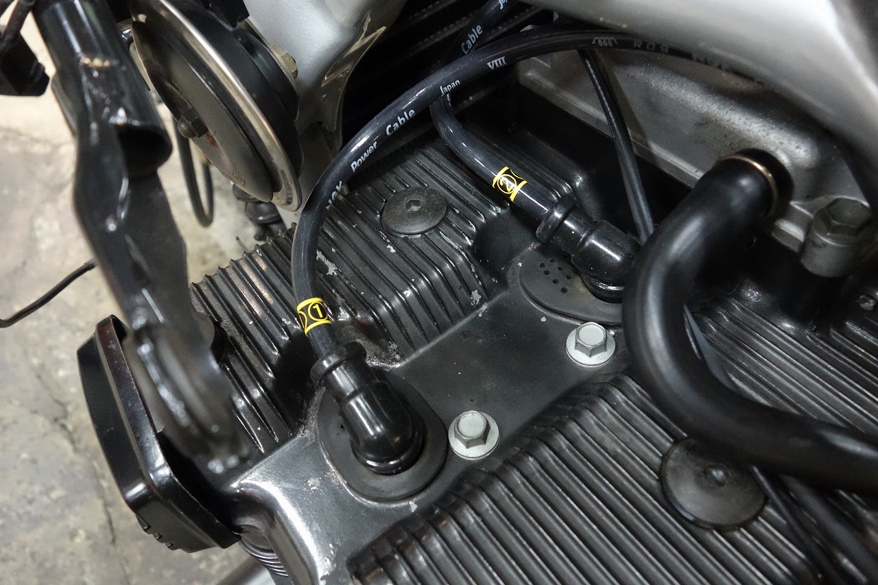
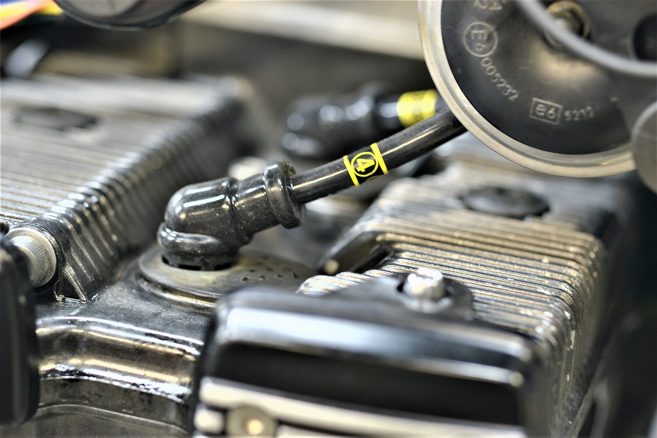
The cord exits forward.
The angle is set to avoid strain.
Try to keep things loose and strain-free for good maintenance access (valve adjustment, plug changes, etc.).
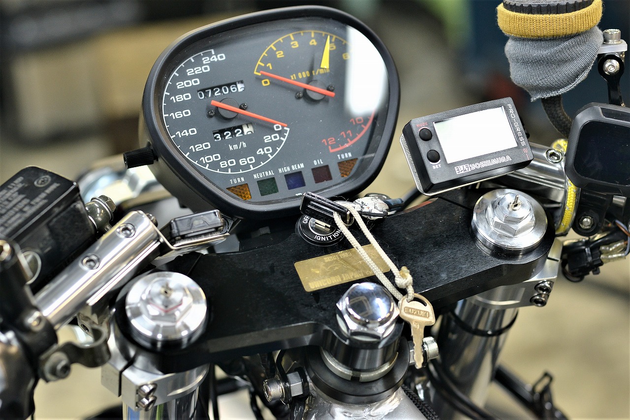
The electrical work is pretty much done… though not bundled yet.
Nearly two full days of wiring work — the progress feels slow and discouraging.
We’re on hold until the wheels and master arrive.